


Lead/Lag Filter
| Parameter | Description | Drive Keyword |
|---|---|---|
|
PL.KP |
Position Loop Proportional Gain |
|
|
VL.ARTYPE# |
Anti-Resonace Filter Type |
|
|
VL.ARZF# |
Filter Zero Cutoff Frequency |
|
|
VL.ARZQ# |
Filter Zero Q Value |
|
|
VL.ARPF# |
Filter Pole Frequency |
|
|
VL.ARPQ# |
Filter Pole Q Value |
|
|
VL.KI |
Velocity Loop Integral Gain |
|
|
VL.KP |
Velocity Loop Proportional Gain |
A lead lag filter is a filter that has 0 dB gain at low frequencies and a user specified gain at high frequencies. The transition frequency where the gain is applied is also user specified.
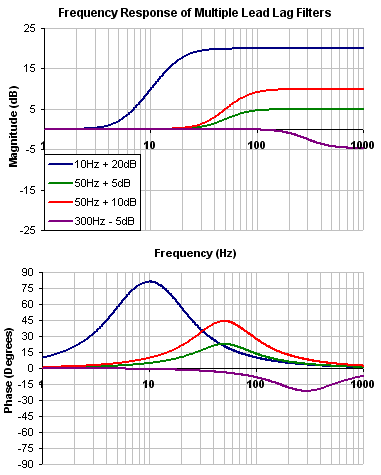
Review: The Controller [C] trace shows the frequency response of VL.KP, VL.KI, PL.KP, AR Filters 1 & 2
Note: Here VL.KP is set to 1.0 so that the gain of the system is at 0dB
A Lead Lag filter is a very powerful and flexible filter. It has two parameters:
-
Center frequency
-
High frequency gain
A Lead Lag is a means of either reducing or increasing high frequency gain. The user specifies the gain change, and a center frequency.
The filter increases/decreases at 40db/decade (second order filter)
Shown to the side is a 1000Hz -15dB Lead Lag
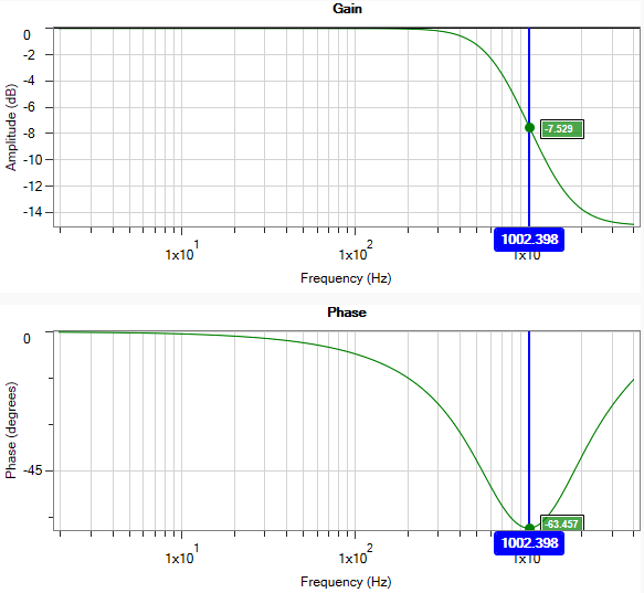
When should a Lead Lag filter be used?
-
Anywhere a Low pass would normally be used
-
Any time a phase “bump” is needed to increase stability at a specific frequency
When comparing the phase loss from a Lead Lag compared with the Low pass, the Lead Lag will always win, with less phase loss! This translates to high stability, and higher system performance.
Note that the peak of the phase dip is at the Center frequency, allowing the user to specify where the phase dip.
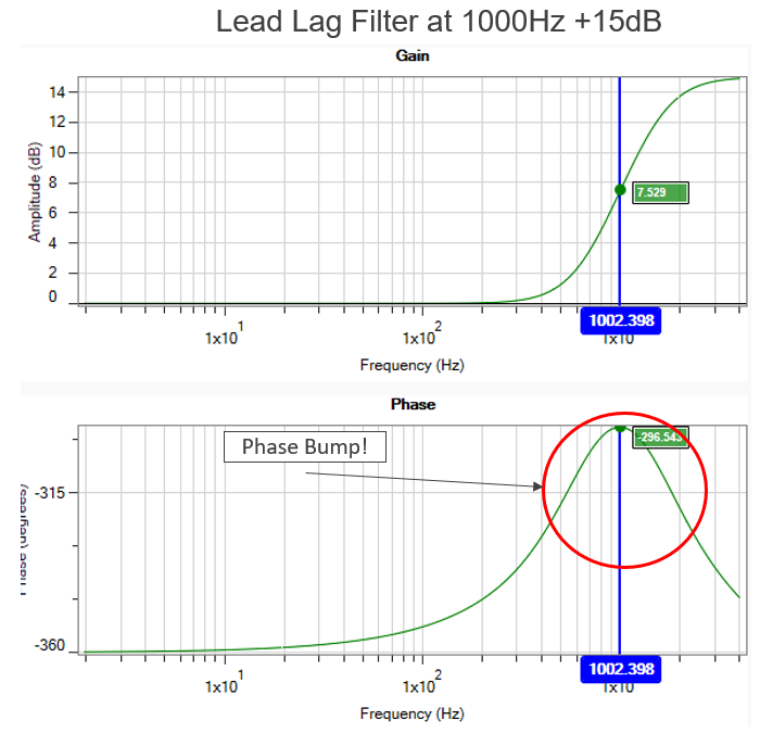
Unlike a Lowpass, a Lead Lag filter can also be used to raise high frequency gain. Often this use is not to raise the gain of the system, but to boost the phase. (Positive Gain = Positive Phase).
There are very few tuning parameters that can boost your phase (add stability), most decrease phase.
A Lead Lag filter can be used to precisely place additional phase where it is needed most.
Need more Phase, just add more gain.
Adjusting Lead/Lag in the Velocity Loop
To specify a Lead Lag filter, you must specify the Center Frequency and high frequency Gain (dB). To do this, see the following example by clicking on the Velocity Loop:
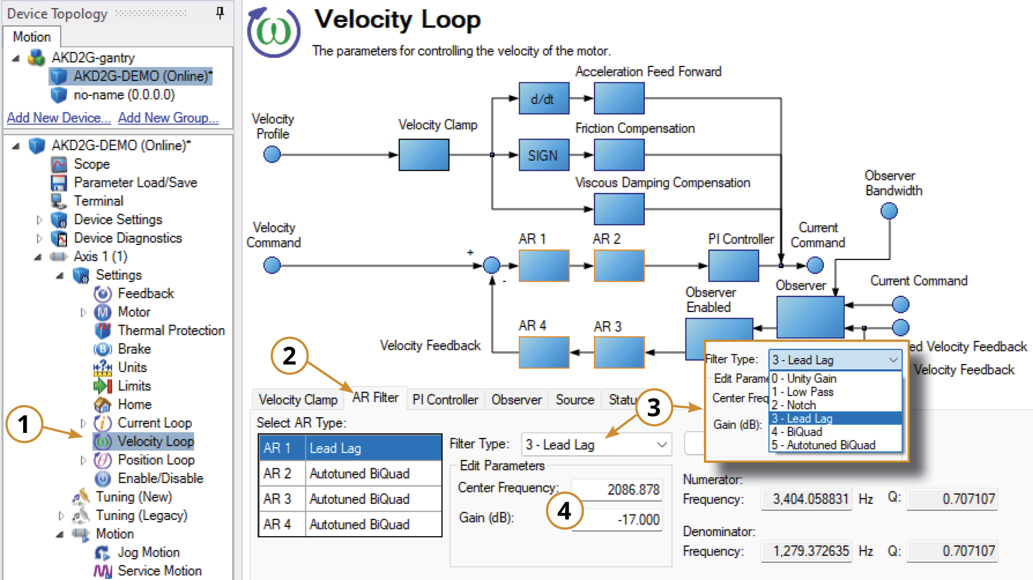
-
Open the Velocity Loop pane.
-
Open the AR Filter tab and select the AR filter that will function as Lead Lag.
-
Select 3 - Lead Lag as the Filter Type.
-
Set the desired Center Frequency and Gain.
Adjusting Lead/Lag Using the Manual Tuning Simulator
Within the Velocity Loop section of the Simulation pane, the filter type and values can be entered for AR filters 1-4.
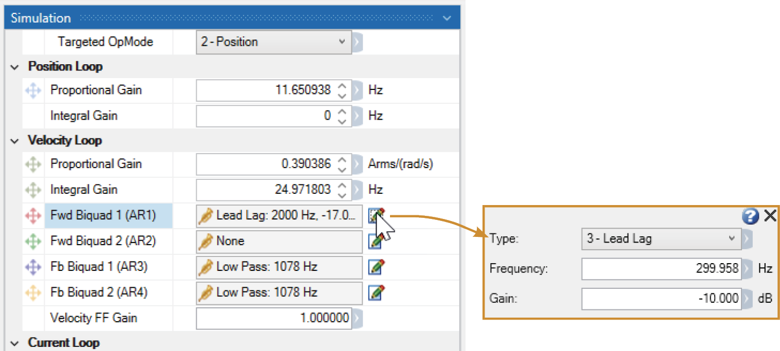
Once the filter type is set to Lead Lag, the Bode Plot Drag+Drop tool may be used to visually adjust the values.
After setting the values within the Simulation pane or using the Drag+Drop sliders, the settings must be written to drive to take effect.


