


Connector pinout
Information to wiring, mating connectors and cables (see "Wiring").
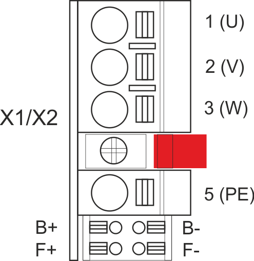
X1 and X2: Motor, Brake, Feedback 1
|
|
|
Pin |
Label |
Signal |
Description |
|---|---|---|---|
|
1 |
U |
U |
Motor phase U |
|
2 |
V |
V |
Motor phase V |
|
3 |
W |
W |
Motor phase W |
|
|
retention latch, shield screw | ||
|
5 |
PE |
PE |
Protective earth |
|
B+ |
B+ |
BR+ |
Motor holding brake + |
|
B- |
B- |
BR- |
Motor holding brake - |
|
F+ |
F+ |
COM+ |
SFD-M + or SFD-3 + or HIPERFACE DSL + |
|
F- |
F- |
COM- |
SFD-M - or SFD-3 - or HIPERFACE DSL - |
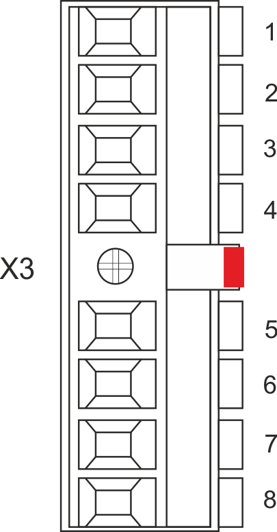
X3: Mains, regen resistor, DC-Bus
|
|
|
Pin |
Label |
Signal |
Description |
|---|---|---|---|
|
1 |
PE |
PE |
Protective earth |
|
2 |
L1 |
L1 |
3~ mains supply L1, 1~ supply L, DC supply + |
|
3 |
L2 |
L2 |
3~ mains supply L2 |
|
4 |
L3 |
L3 |
3~ mains supply L3, 1~ supply N, DC supply - |
|
5 |
Ri |
RBint |
internal regen resistor |
|
6 |
RE |
-RB |
external regen resistor - |
|
7 |
+DC |
+DC (+RBext) |
DC Bus link+ and/or external regen resistor + |
|
8 |
-DC |
-DC |
DC Bus link - |
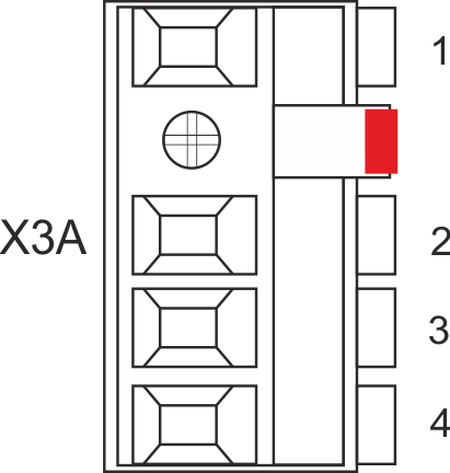
X3A/X3B: Mains, regen resistor, DC-Bus
|
|
X3A
|
Pin |
Label |
Signal |
Description |
|---|---|---|---|
|
1 |
PE |
PE |
Protective earth |
|
2 |
L1 |
L1 |
3~ mains supply L1, 1~ supply L, DC supply + |
|
3 |
L2 |
L2 |
3~ mains supply L2 |
|
4 |
L3 |
L3 |
3~ mains supply L3, 1~ supply N, DC supply - |
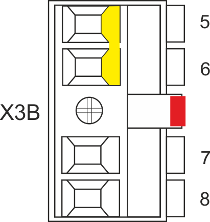
X3B
|
Pin |
Label |
Signal |
Description |
|---|---|---|---|
|
5 |
Ri |
RBint |
internal regen resistor |
|
6 |
RE |
-RB |
external regen resistor - |
|
7 |
+DC |
+DC (+RBext) |
DC Bus link+ and/or external regen resistor + |
|
8 |
-DC |
-DC |
DC Bus link - |
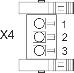
X4: Second Brake
|
|
Use with single axis servo drives and Safety Option |

|
|
|
Pin |
Signal | Description |
|---|---|---|
|
1 |
PE |
Protective earth |
|
2 |
BR2- |
Second (external) brake - |
|
3 |
BR2+ |
Second (external) brake + |
X5: Feedback 2
|
|
Use with single axis servo drives and Safety Option |

|
|
|
Pin |
Signal | Description |
|---|---|---|
|
1 |
PE |
Protective earth |
|
2 |
COM2- |
Second SFD-M/SFD-3 - or Second/Safe HIPERFACE DSL - |
|
3 |
COM2+ |
Second SFD-M/SFD-3 + or Second/Safe HIPERFACE DSL + |
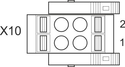
X10: 24 VDC
|
|
|
Pin |
Signal | Description |
|---|---|---|
|
1 |
+ 24 V |
+24 VDC supply voltage, PELV |
|
2 |
GND |
Ground for 24 VDC supply voltage, PELV |
X11, X12: EtherNet Fieldbus
|
|
|
|
Pin |
Signal | Description |
Pin |
Signal | Description |
|---|---|---|---|---|---|
|
1 |
Tx+ |
Transmit + |
5 |
Term. |
Termination |
|
2 |
Tx- |
Transmit - |
6 |
Rx- |
Receive - |
|
3 |
Rx+ |
Receive + |
7 |
Term. |
Termination |
|
4 |
Term. |
Termination |
8 |
Term. |
Termination |
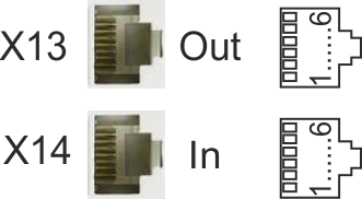
X13, X14: CAN bus (optional)
|
|
|
Pin |
Signal | Description |
Pin |
Signal | Description |
|---|---|---|---|---|---|
|
1 |
n.c. |
not used |
4 |
CAN_low |
CAN bus low signal |
|
2 |
Shield |
Chassis |
5 |
CAN_GND |
CAN bus ground |
|
3 |
CAN_high |
CAN bus high signal |
6 |
n.c. |
not used |
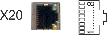
X20: Service
|
|
|
Pin |
Signal | Description |
Pin |
Signal | Description |
|---|---|---|---|---|---|
|
1 |
Tx+ |
Transmit + |
5 |
Term. |
Termination |
|
2 |
Tx- |
Transmit - |
6 |
Rx- |
Receive - |
|
3 |
Rx+ |
Receive + |
7 |
Term. |
Termination |
|
4 |
Term. |
Termination |
8 |
Term. |
Termination |
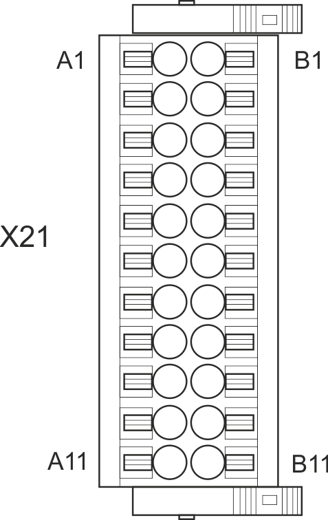
X21: I/O, Feedback 4
|
|
Digital I/O connectivity
|
Pin |
Signal |
Description |
|---|---|---|
|
A1 |
Analog-In (AIN) 1 + |
Analog Input +/- 10 V |
|
A2 |
Analog-In (AIN) 1 - |
|
|
A3* |
Digital-In (DIN) 1 |
Fast, isolated, sink, type EN 61131-2 type 1 |
|
A4* |
Digital-In (DIN) 2 |
Fast, isolated, sink, type EN 61131-2 type 1 |
|
A5 |
Digital-In (DIN) 3 |
Slow, isolated, sink, type EN 61131-2 type 1 |
|
A6 |
Digital-In (DIN) 4 |
Slow, isolated, sink, type EN 61131-2 type 1 |
|
A7 |
Digital-In (DIN) 5 |
Slow, isolated, sink, type EN 61131-2 type 1 |
|
A8 |
Digital-In (DIN) 6 |
Slow, isolated, sink, type EN 61131-2 type 1 |
|
A9 |
Digital-In (DIN) 7 |
Slow, isolated, sink, type EN 61131-2 type 1 |
|
A10 |
Digital-In (DIN) 8 |
Slow, isolated, sink, type EN 61131-2 type 1 |
|
A11 |
|
Slow, isolated, sink, fail-safe, functional safety input 1 STO axis 1 channel A |
|
B1 |
Analog-Out (AOUT) 1 |
Analog Output, 0 to +10 V |
|
B2 |
AGND |
Ground for analog I/O |
|
B3 |
+24 V |
+24 VDC for digital I/O and STO |
|
B4 |
DGND |
Ground for digital I/O and STO |
|
B5 |
Digital-Out (DOUT) 9 + |
Relay contact, normally open, 24 VDC, 1A |
|
B6 |
Digital-Out (DOUT) 9 - |
Relay contact, normally open, 24 VDC, 1A |
|
B7 |
|
Isolated, high-side, |
|
B8 |
|
Isolated, high-side, |
|
B9 |
|
Isolated, high-side, |
|
B10 |
|
Isolated, high-side, |
|
B11 |
|
Slow, isolated, sink, fail-safe, functional safety input 2 STO axis 1 channel B |
*Feedback 4 connectivity, Step/Direction CW/CCW (input)
|
Pin |
Signal | Description |
|---|---|---|
|
A3 |
Step, CW |
Fast, isolated, sink, type EN 61131-2 type 1 |
|
A4 |
Direction, CCW |
Fast, isolated, sink, type EN 61131-2 type 1 |
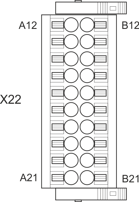
X22: I/O, EEO2, Feedback 5
|
|
Digital I/O connectivity
|
Pin |
Signal | Description |
|---|---|---|
|
A12 |
|
Slow, isolated, sink, fail-safe, functional safety input 3 STO axis 2 channel A |
|
A13 |
Digital-In (DIN) 9 |
Slow, isolated, sink, type EN 61131-2 type 1 |
|
A14 |
Digital-In (DIN) 10 |
Slow, isolated, sink, type EN 61131-2 type 1 |
|
A15 |
Digital-In (DIN) 11 |
Slow, isolated, sink, type EN 61131-2 type 1 |
|
A16 |
Digital-In (DIN) 12 |
Slow, isolated, sink, type EN 61131-2 type 1 |
|
A17 |
AGND |
Ground for analog I/O |
|
A18 |
Analog-In (AIN) 2+ |
Analog Input, +/- 10 V |
|
A19 |
Analog-In (AIN) 2- |
|
|
A20* |
Digital-In/Out (DIO) 1 + |
RS485 input or output |
|
A21* |
Digital-In/Out (DIO) 1 - |
RS485 input or output |
|
B12 |
|
Slow, isolated, sink, fail-safe, functional safety input 4 STO axis 2 channel B |
|
B13 |
Digital-Out (DOUT) 5 |
Isolated, high-side, 100 mA |
|
B14 |
Digital-Out (DOUT) 6 |
Isolated, high-side, 100 mA |
|
B15 |
Digital-Out (DOUT) 7 + |
Fast, isolated, sink or source, 100 mA |
|
B16 |
Digital-Out (DOUT) 7 - |
|
|
B17 |
Digital-Out (DOUT) 8 + |
Fast, isolated, sink or source, 100 mA |
|
B18 |
Digital-Out (DOUT) 8 - |
|
|
B19 |
Analog-Out (AOUT) 2 |
Analog Output, 0 to +10 V |
|
B20* |
Digital-In/Out (DIO) 2 + |
RS485 input or output |
|
B21* |
Digital-In/Out (DIO) 2 - |
RS485 input or output |
|
*Feedback 5 (input)
|
*EEO2 (output)
|
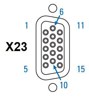
X23: I/O, EEO1, Feedback 3
|
|
Feedback 3 connectivity (input)

CL = CLOCK, D = DATA, S = SENSE, Th = Thermal control, Z = Zero
█ = DC Terminated, can be overridden with DIO#.TERM
█ = Optional
█ = Information digitally communicated on COM+/- channel.
|
EEO1 connectivity (output)
|
Digital I/O connectivity
|
X41: SFA Feedback converter, EEO3/EEO4 (accessory)

|
|
Feedback 1/2 connectivity (input)

CL = CLOCK, D = DATA, S = SENSE, Th = Thermal control, Z = Zero
(1) : Resolver with AKD2G-CON-SFA-R00 only, all other feedback devices with AKD2G-CON-SFA-E00 only
- █ = DC Terminated, can be overridden with "DIO#.TERM"
- █ = Optional
- █ = Information digitally communicated on COM+/- channel.
EEO3 / EEO4 Connectivity (output)
| X41 Pin |
Incremental Encoder |
|---|---|
| 6 | Zero+ |
| 7 | Zero- |
| 11 | 0 V |
| 12 | A + |
| 13 | A- |
| 14 | B+ |
| 15 | B- |