


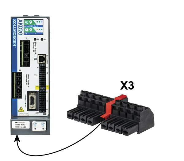
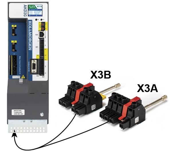
DC Bus link connector X3/X3B
The DC bus link can be connected in parallel so that the power returned from slowing down motors is divided between all the servo drives that are connected to the same DC bus link circuit. Every servo drive must have its own power connection to mains voltage sharing the same branch, over current protection devices, even if the DC bus link is used. Servo drives being operated very often should be placed beside servo drives, which need energy. That reduces current flow on longer distances.
|
|
The servo drives can be destroyed if DC bus link voltages are different. Only drives with mains supply that share the same AC branch, over current protection devices (identical mains supply voltage) may have the DC bus links interconnected. Interconnection of DC bus links works best in systems powered by 3-phase AC or DC power. Consult Kollmorgen for DC bus linking with single phase AC power input. |
|
|
The sum of the application currents in the connected in parallel DC bus wires must not exceed 48 A. Wiring: Use 6mm² unshielded single cores with a max. length of 200 mm; use 6mm² shielded cables for longer lengths. In this case no fuse for line protection is required. |


|
|
|

|
|
Pin |
Label |
Signal |
Description |
|---|---|---|---|
|
7 |
+DC |
+DC |
DC Bus link positive |
|
8 |
-DC |
-DC |
DC Bus link negative |
|
|
In addition to the sum of the axes currents (I1...n) in parallel DC bus groupings being less than 48 A, the sum of the AC input currents (A1...n) must be less than 30 A (32 A when semiconductor fuses are used). The maximum number of axes is limited to 8 servo drive enclosures per group installation. Group AC fusing and breaker guidelines should also be followed for DC bus groupings.(see "AC supply, group of drives, line fusing") |

Fusing
External regen fusing FB1/FB2 (see "Fusing and Wiring"). DC bus link fusing depends on topology (see Wiring example with T connectors).
|
Wiring |
Ampere |
Ampere |
Example Eaton: |
Example Mersen: |
|---|---|---|---|---|
| AKD2G-Sxx-6V | ||||
|
Group: Fgroup |
max. 30 A |
na |
DFJ-30 |
HP6M30 |
|
Busbar: Fbus |
max. 15 A |
na |
DFJ-15 |
HP6M15 |
| AKD2G-Sxx-7V | ||||
|
Group: Fgroup |
max. 30 A |
FWP-30B |
HP10M30 |
|
|
Busbar: Fbus |
max. 15 A |
FWP-15B |
HP10M15 |
|
|
|
Follow group AC fusing and breaker guidelines when sharing or grouping regen resistors. (see "AC supply, group of drives, line fusing") |
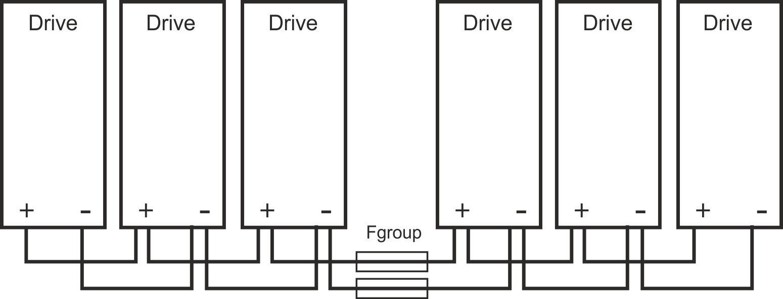
Wiring example with T connectors
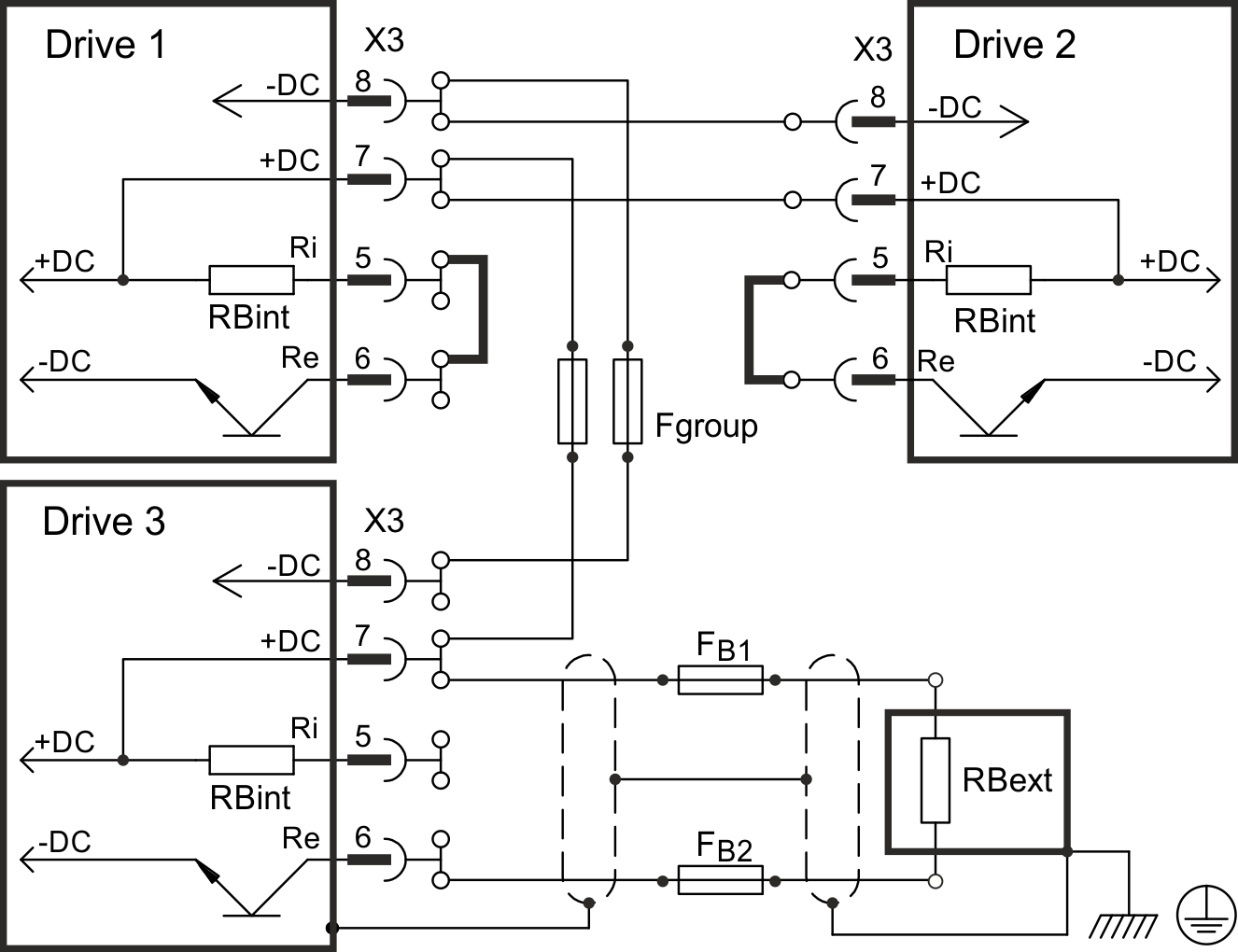
Note: T connectors are not available for 7V24 drives.
Without DC Bus fuses, other devices can become damaged or destroyed if, for example, a device fails due to an internal short circuit. If multiple drives are connected in parallel, then it is usual to insert DC Bus fuses (Fgroup) between groups of drives (with a group consisting of two or three devices, depending on the current) in order to limit any possible resulting damage. Fgroup fuses cannot avoid damage by current peaks completely.
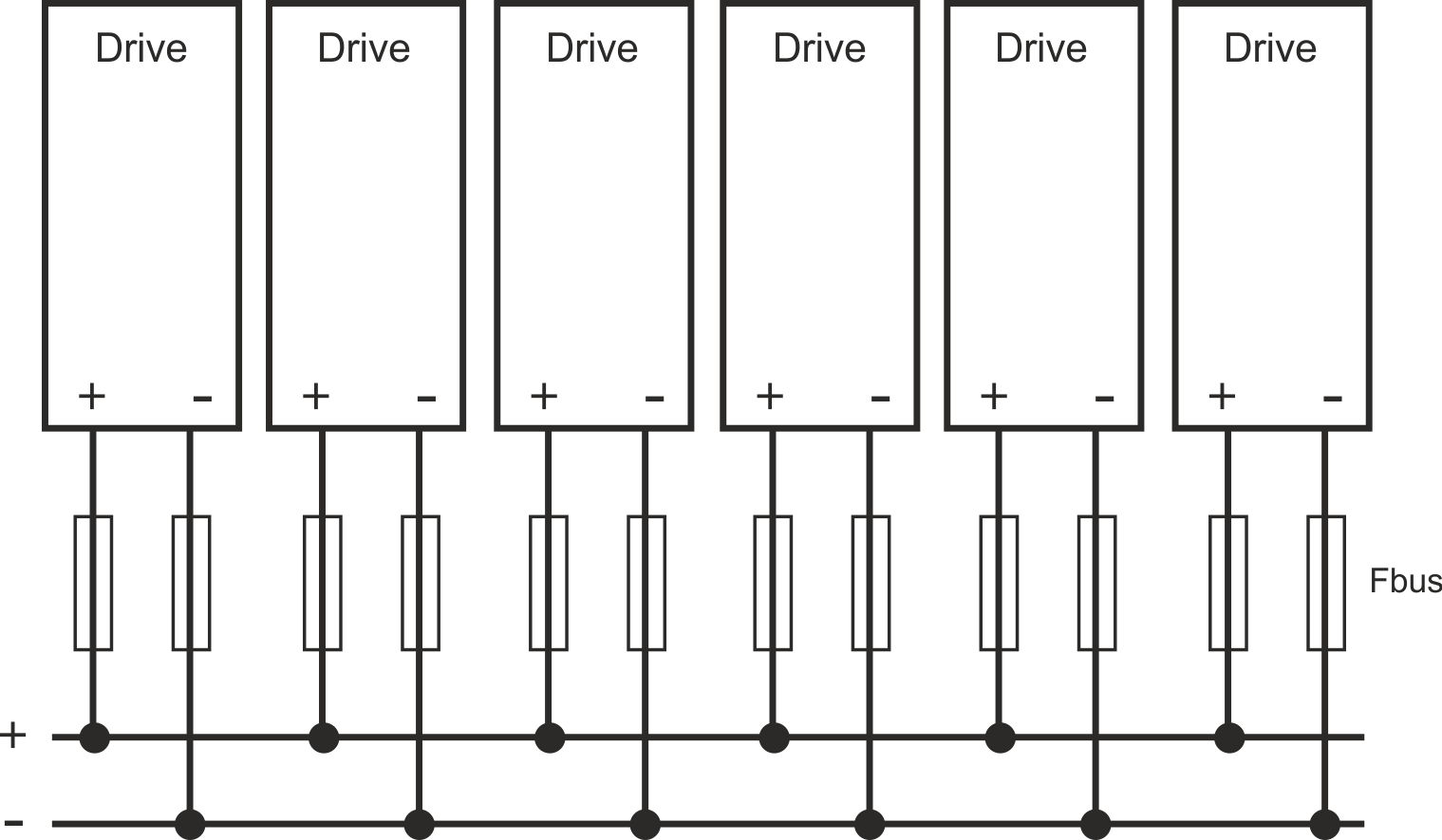
Wiring example with busbar
If a device fails in this system due to a short-circuit, only its fuses (Fbus) are tripped and the rest of the network continues uninterrupted. The solid busbars can conduct significantly larger currents than T connectors, because the compensating current does not flow through the connector as above.