SBT (Safe Brake Test)
Safe Brake Test description for drive option Functional Safety 2 or 3.
Description
The function SBT (Safe Brake Test) can be used for testing the brakes connected to X1, X2 or X4 of the AKD2G. SBT is carried out by applying a configured torque against the closed brake and supervising the motion on the connected axis. The test is successful if the axis motion does not exceed a parameterized tolerance. If the axis motion exceeds the tolerance, the test is failed and therefore the safety functions using the brake are lost. After a failed brake test, safe brake operation cannot be assumed anymore. Brake replacement or service will be necessary.
- SBT is a diagnostic function for holding brakes. In order to operate brakes (SBC) that are part of a safety function (PLd / SIL2 or higher), frequent tests with SBT are required.
- SBT must be triggered regularly by the end customer.
- SBT considers the derating factor for brakes used in safety functions.
- During SBT, 130% of the max. possible application torque will be applied to the brake. Additional forces caused by vertical loads will be taken into account automatically.
- Brake slippage will be detected with a resolution of at least 1°.
- Two brakes can be assigned to one axis. Each brake can be configured with an independent slippage tolerance.
- SBT is only functional with SBC.
- SBT does not lead to wear of the brakes.
Important Notes
Execute a brake test
- at least every 8 hours,
- at the start of a machine or at the transition to operation mode using the brake,
- after long standstill of the machine,
- after drive reboot,
- after brake service or replacement.
Depending on the target SIL / PL of the safety function that is performed by the brakes, it can be necessary to carry out SBT more often. In high safety demand applications (SIL3 / PLe, DC = high), it can be necessary to execute SBT every time prior to demand. For example if access to a dangerous area is prohibited by a safety interlock, SBT must be executed successfully before access can be granted.
Restrictions
The maximum motion for the brake during safe brake test (see “Maximum Motion” parameters (➜ # 1, Related Parameters)) cannot be set to a greater or equal value than 10800 arcminute. Otherwise, the SMM will return an error code once SBT function is started. The error code can be read by the keyword AXIS#.SAFE.SBT.ERROR, which will report “0x6 – SMM System Error”.
In general, it is expected to set the maximum motion for the “tested” brake as small as possible to prevent any mechanical hazards when the brake loses its holding function. However, an application might need a larger tolerance window because of a mechanical gearing between encoder and motor shaft.
The maximum slippage velocity in [RPM] is calculated by:
(10800 [arcmin] – “Max. Motion” [arcmin]) * 600 / 216
Example:
- For “Max. Motion” = 300 arcmin (5°), the max. slippage velocity is
(10800-300) * 600/216 = 29167 rpm. - For “Max. Motion” = 7200 arcmin (120°) , the max. slippage velocity is
(10800-7200) * 600/216 = 10000 rpm.
|
|
The user has to consider for his application the worst case max. acceleration of motor shafts load including the additional "applied" test torque of the drive during SBT. |
Preconditions for a brake test:
- The motor is at standstill.
- The tested brake is released.
- The drive is enabled.
- STO is not active.
Encoder requirements
|
|
The encoder verification is not required for safe encoders that can be configured on drives with option FS3. |
The SBT function can be executed with any encoder type. However, the encoder shall have at least a resolution and accuracy of 1 degree.
Encoder verification:
The user shall verify that the encoder works properly by his application. As example the following types of machine motion can be used to verify the function of the encoder:
- Perform a home move which includes a physical motion.
- A position move of at least 1 mechanical revolution of the encoder.
- A relative move to reach the start position of SBT.
After a long downtime of the machine, the encoder verification shall be repeated.
Current measurement verification
The verification check of drive current measurement should be done during machine commissioning and during re-commissioning due to changes such as replacement of the drive or firmware update.
The current measurement should verify expected current reported by the drive when holding a reference load. A small movement may be needed to overcome static friction.
Function Input / Output Variables

Inputs
- SBT Activate can be activated by
- EtherCAT, CANopen
- Digital input (must be mapped)
- WorkBench
Outputs
- SBA State: logical status providing information on SBT. Can be mapped to a safe output and retrieved through FSoE status word.
0 = SBT execution necessary or failed in last attempt
1 = SBT was executed successfully within the parameterized period - SBT State: for status information on the actual brake condition see (➜ # 1, AXIS#.SAFE.SBT.STATE).
Number of Instances
One instance per axis.
Activation
- By a non safe fieldbus: EtherCAT or CANopen SDO
- By a non safe digital input (DIGITAL-IN1 to DIGITAL-IN12, (see "Digital Inputs")).
- By WorkBench
Related Parameters
Safety parameters
|
Name |
Variables |
Default |
Parameter |
|---|---|---|---|
|
Function Activation |
- |
0 (Never active) |
|
|
Maximum Time Interval |
- |
480 min |
|
|
Max Application Load |
- |
1000 mA |
|
|
Maximum Motion 1st Attached Brake |
- |
300 arcmin |
|
|
Maximum Motion 2nd Attached Brake |
- |
300 arcmin |
|
|
Torque Duration |
- |
500 ms |
Diagnostic parameters
|
Name |
Variables |
Default |
Parameter |
|---|---|---|---|
|
SBT Actual Status |
- |
- |
|
|
SBT Move |
- |
- |
|
|
SBT SBA Active |
- |
- |
|
|
SBT Error |
- |
- |
|
|
Brake SBT Elapsed |
- |
- |
|
|
Brake SBT State |
- |
- |
Timing
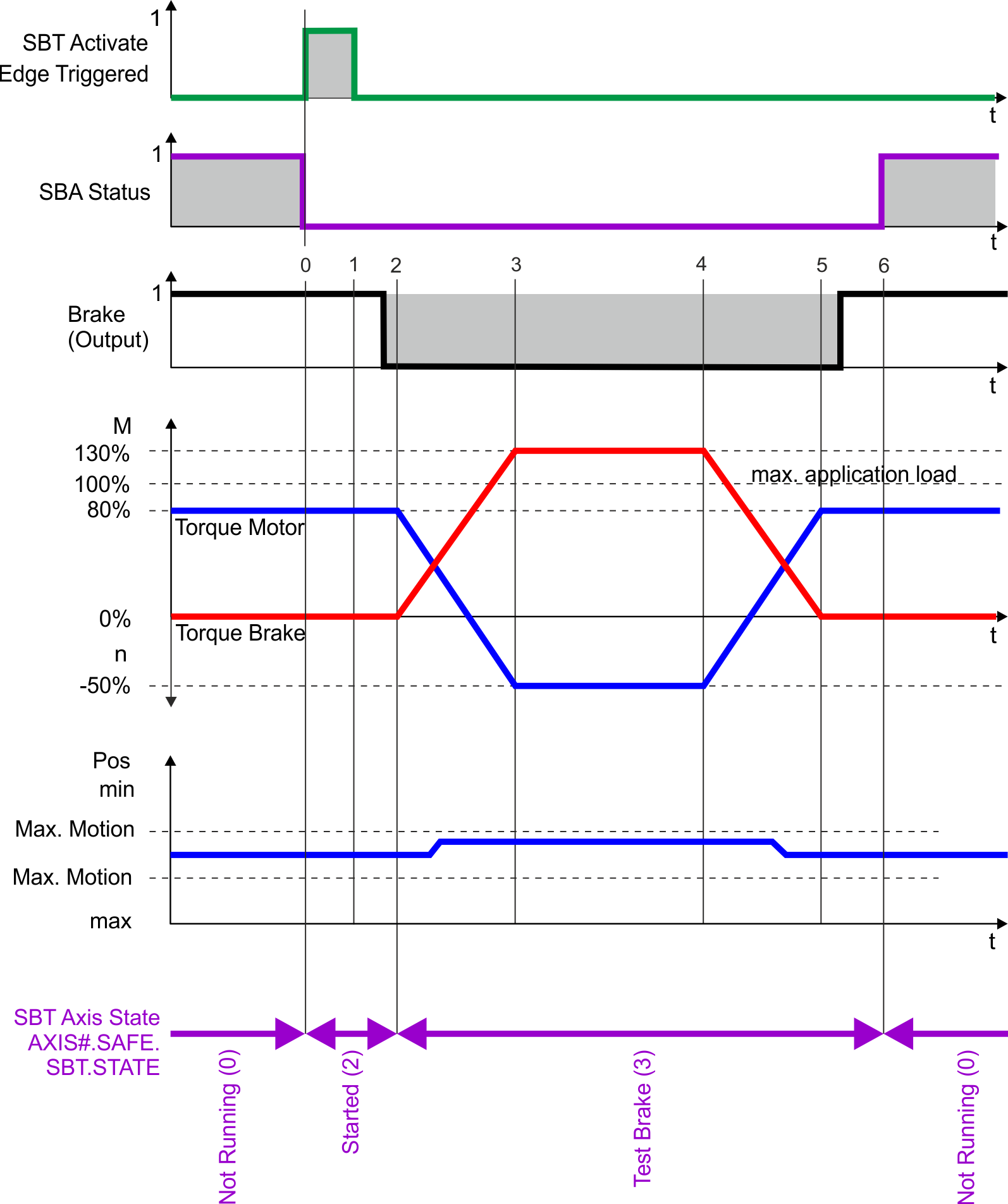
|
Timing |
max |
Remarks |
|---|---|---|
|
t0 |
|
Start SBT |
|
t0 to t1 |
200 ms |
Measuring actual application load on motor |
|
t1 to t2 |
300 ms |
Brake applies |
|
t2 |
|
Brake is applied. Position monitoring is started. Drive is switched to torque mode internally. |
|
t2 to t3 |
1/3 * (t3 to t4) |
Ramp-up to apply 130% torque on the brake |
|
t3 to t4 |
Configurable |
Torque duration |
|
t4 to t5 |
1/3 * (t3 to t4) |
Ramp-down torque on the brake |
|
t5 to t6 |
300 ms |
Release brake |
|
t6 to t0 |
Configurable |
Maximum time interval between tests |
Setup in WorkBench
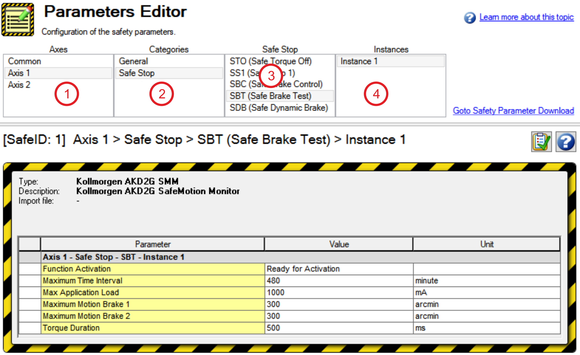
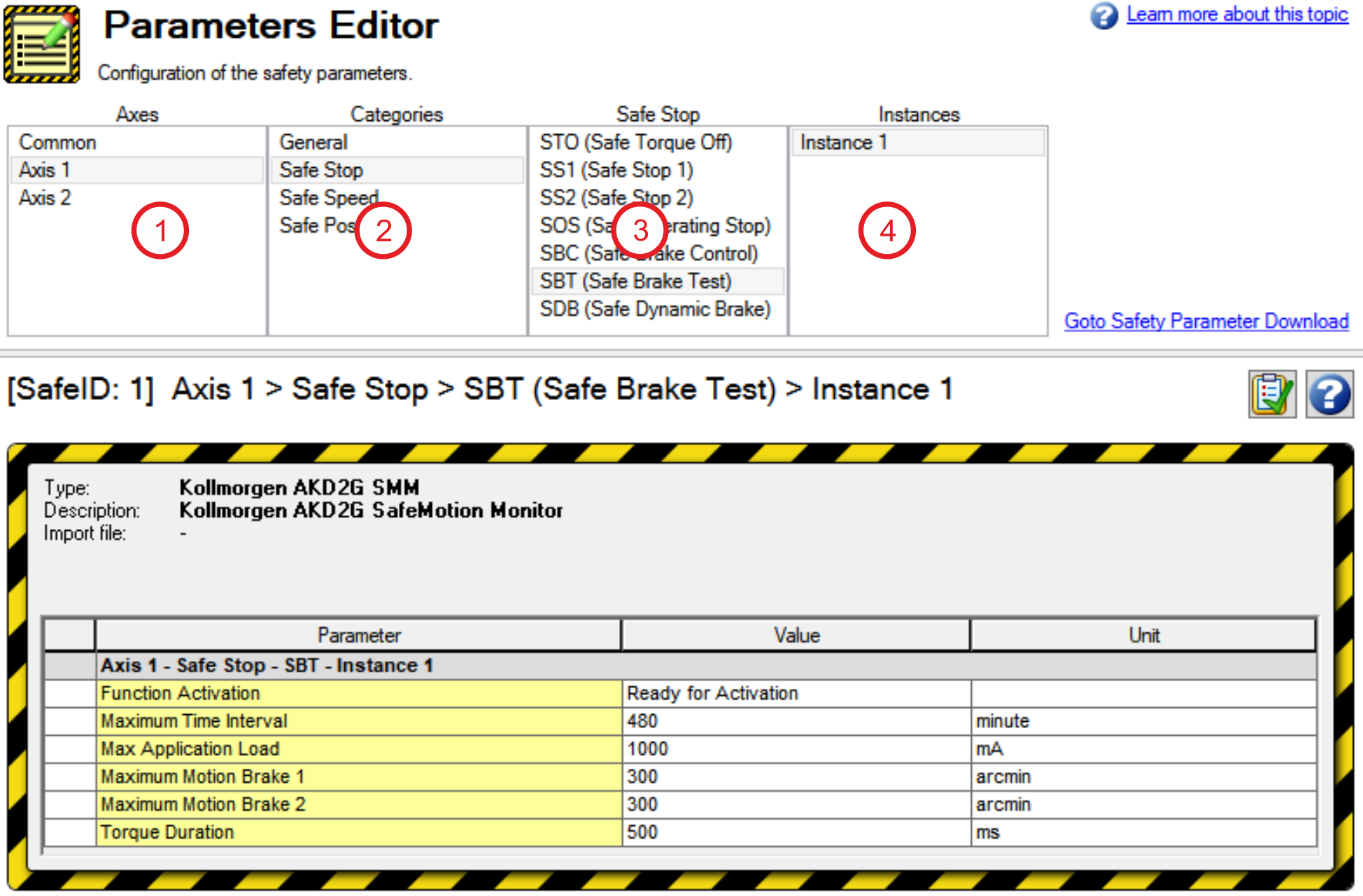
Select Safety Parameterization view (see "WorkBench Safety Function Setup").
Choose the axis (1), category (2) and SBT function (3). The instance number (4) is not applicable for SBT.
Fault Reaction / Failure Messages
If not all the preconditions are fulfilled and SBT is requested, the SBT button will be grayed out:
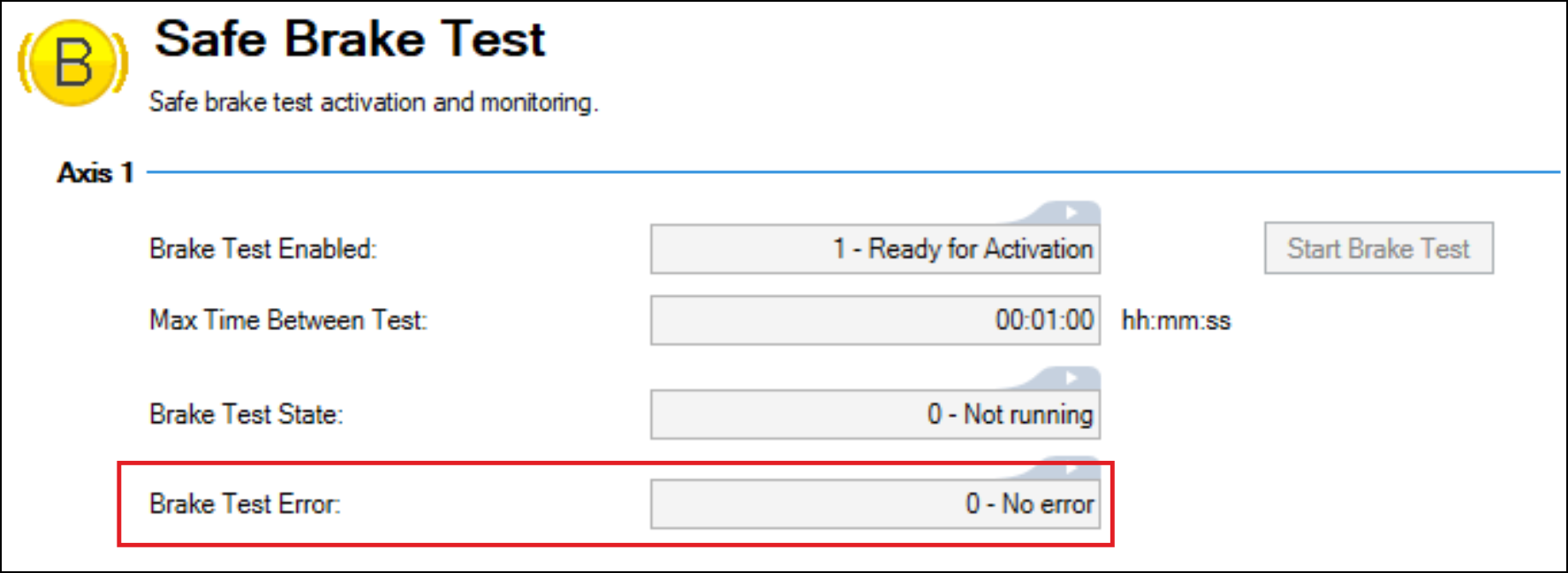
When a brake test fails, further operation shall be prohibited by means of an external safe PLC. SBA will remain 0 and the Safety Diagnostics will show a ”Brake Slippage Occurred”:

A controlled stop will be executed immediately when a brake slippage is detected during the brake test. The drive remains enabled.
Safety State / Status Signals
Status of each axis and the assigned brakes can be observed in the SBT diagnostics view.
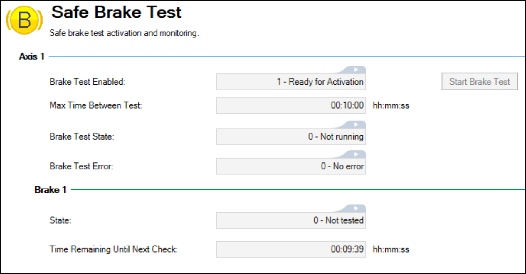
The view gives information about:
- Status, if the test is running or not
- Test result (Not tested, Failed, Passed)
- Time until next and in-between test
- Status information on the test, if and which error occurred
If a brake test is not executed within the parameterized time interval, the Safe Brake Test Diagnostics will inform that the test validity is expired.

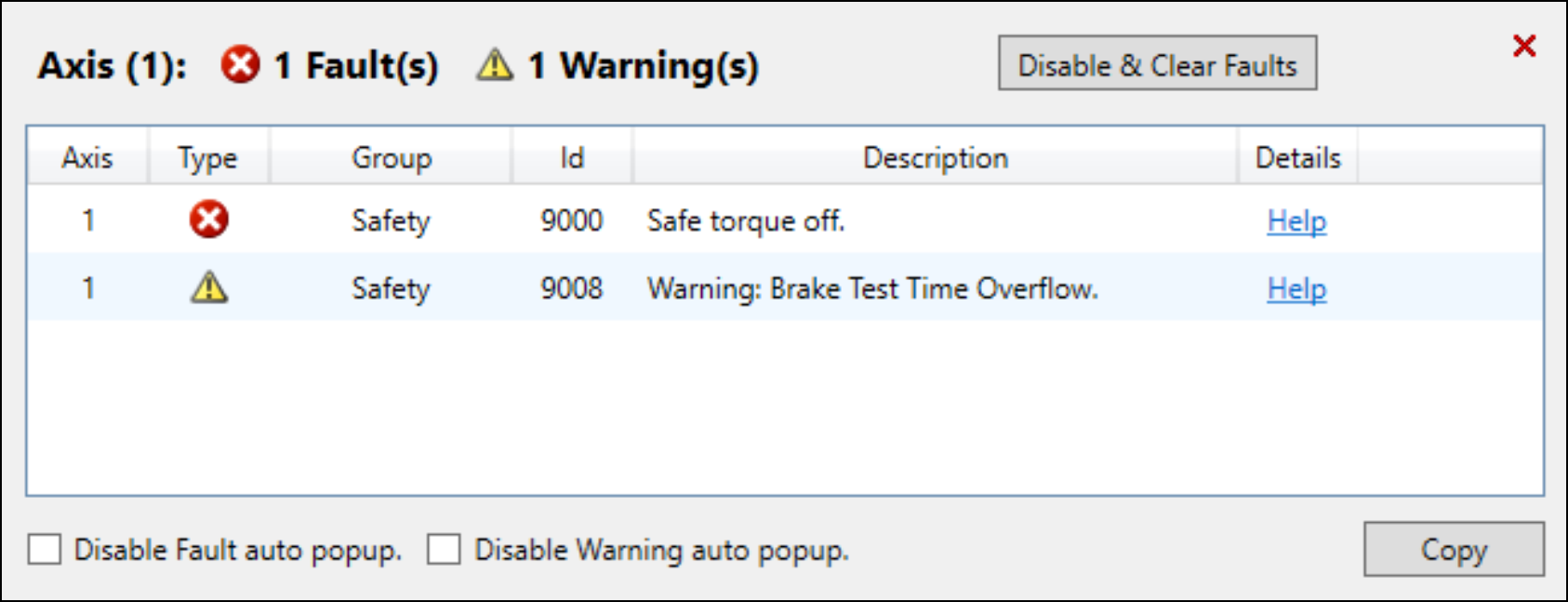
The warning 9008 “Brake Test Time Overflow” will be issued.
