


 About Actions
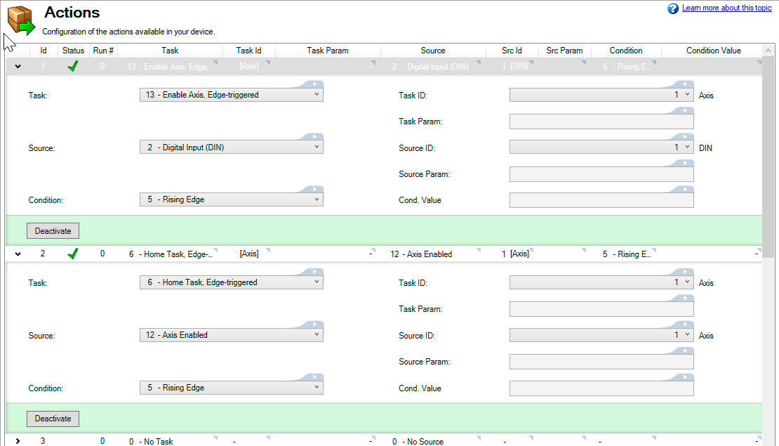
Actions are used to setup tasks the drive will perform based on selected sources and conditions. An example of how Actions may be used is to enabling an axis any time it is triggered by a rising edge on a particular digital input.
Up to 32 actions may be configured. Each action has a minimum of 32 elements, which may also have additional requirements.
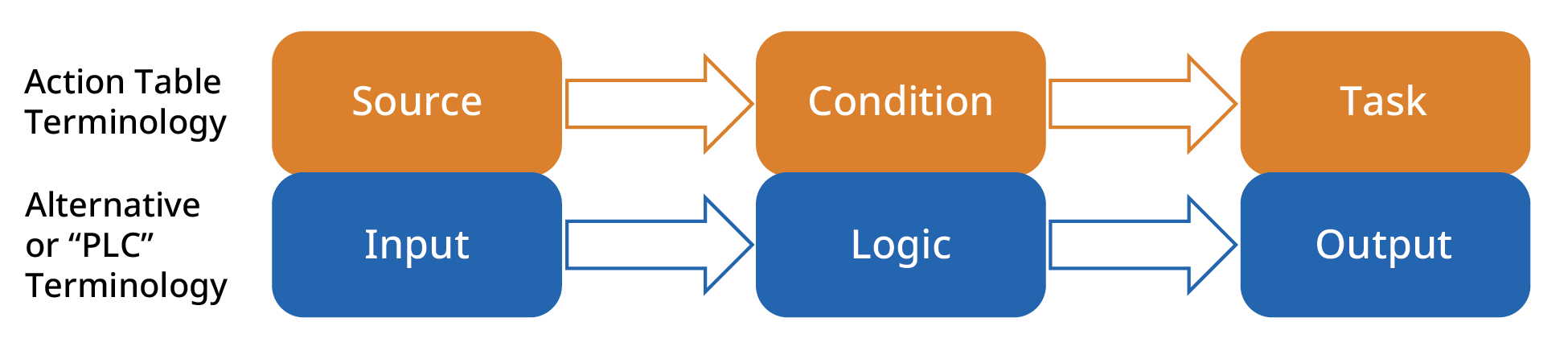
Actions Table Terminology Compared to PLC Terminology
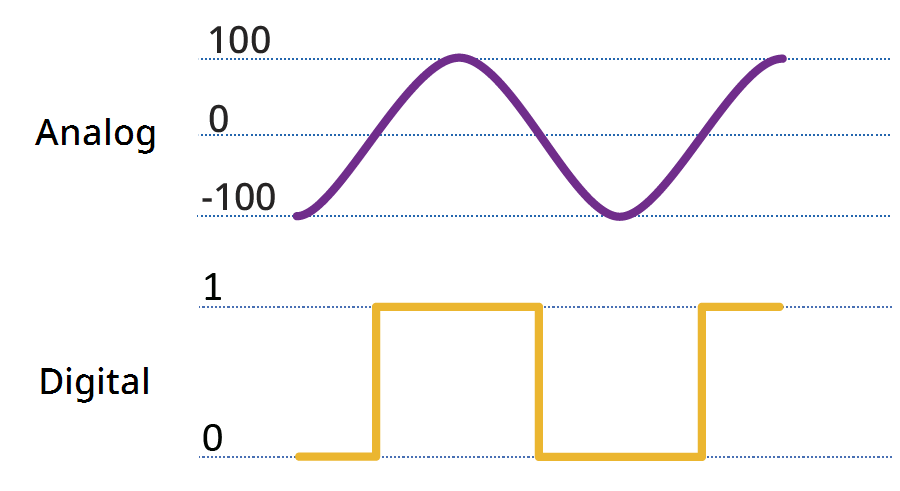
Input Signal Types
Input signals are either analog or digital. The AKD2G supports up to 12 digital inputs (DIN1-12) and 2 analog inputs (AIN1-2).
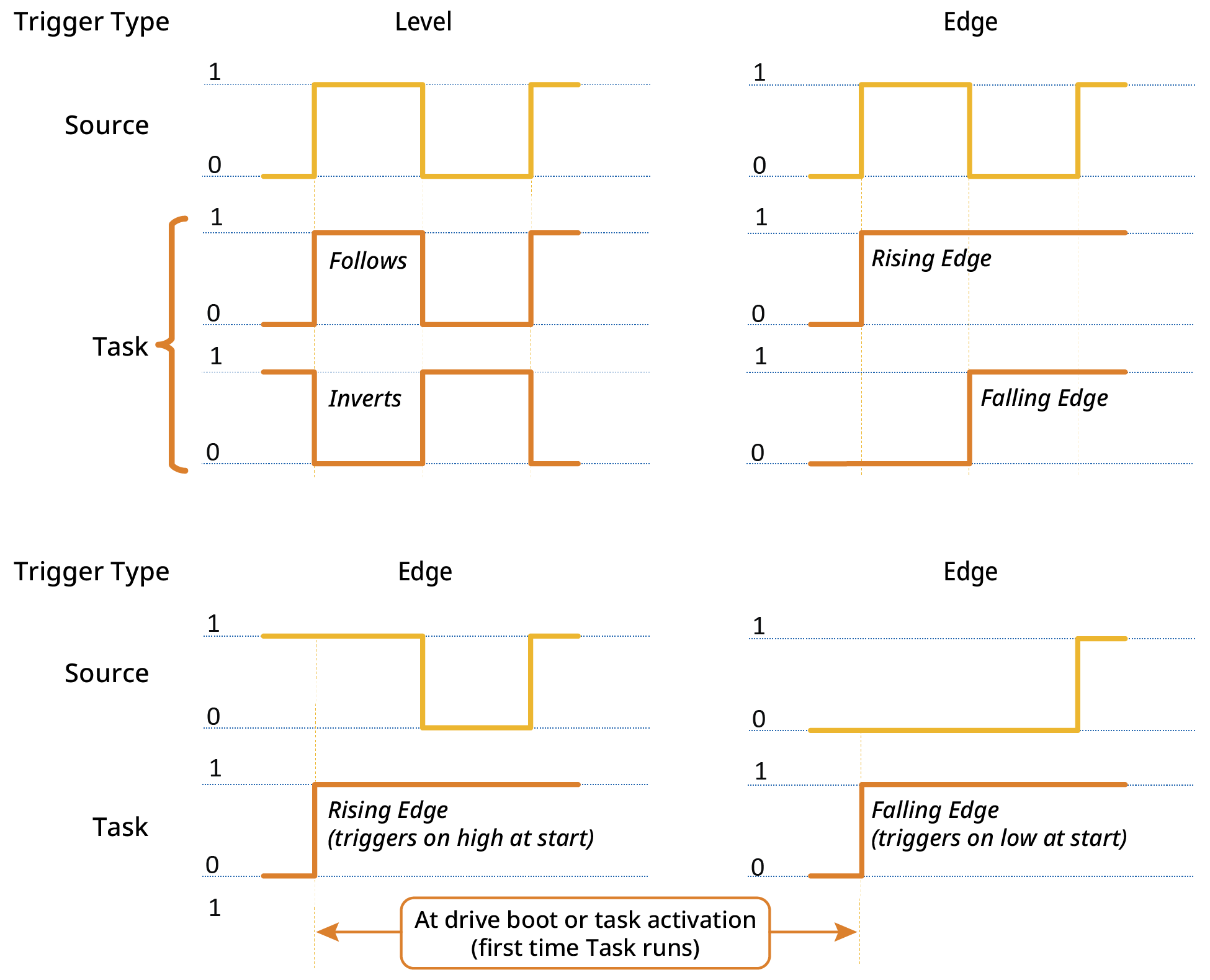
Input Signal Trigger Conditions
An Action Task is triggered when the source input signal meets the criteria of the selected condition.
Digital Input Triggers
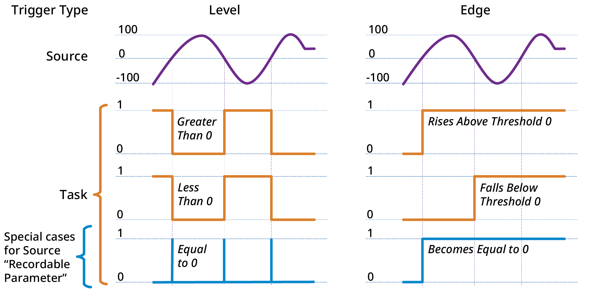
Analog Input Triggers
Action Execution
Actions are executed sequentially, top to bottom, starting at Action 1, at a 4kHz rate.
Certain tasks, like clearing faults, may take a longer than 4kHz cycle to execute. These tasks will be initiated in a low priority thread. If the task is triggered a second time while the task is already running, it will not be queued to run again and the action will be ignored until the running task is complete.
Scanning of the table does not begin until boot up has completed. Any edges occurring on any signal will be ignored until this time. In addition, edge triggered actions will not be executed if the test condition is already true at boot time.
To avoid inconsistent behavior, an action is automatically disabled when any of its fields are edited. Reactivate the action after editing any of its field settings.
Chaining Actions
Actions are executed sequentially so they can be configured to execute a chain of actions.
For example, if Action 1 enables axis 1 when mains ready is true, then Action 2 can be configured to start homing when axis 1 is enabled. When Action 1 completes its task, it triggers Action 2 to execute.
See Also
Actions View Interface Reference, Actions Table Example, Execution, & Errors