Kollmorgen Essentials Motor Shaft Key Kit - Installation
|
|
|
|
|
|


Procedure
- Verify all kit contents and required tools are available for kit installation.
See Kollmorgen Essentials Motor Shaft Key Kit - Contents and Required Tools. - Remove the power to the
- Inspect all surfaces for any damage, including nicks or burrs.
If nicks or burrs are present, use an abrasive cloth to remove. - Place the protective pad on a firm, flat, horizontal surface.
- Place the
- Using either the half/modified key or full key, insert the keyway into the keyway slot in the shaft.
- Using the plastic- or rubber-lined pliers, press the keyway into the shaft as far as it can go. (Figure 1)
Press along length of key to ensure it is fully seated along the entire length of the keyway. - Support the shaft during the installation process.
- Excessive radial loads may damage the motor bearings or rotor assembly.
- Kollmorgen is not liable for injury or damages occurred during any installation process.
- When the shaft key is installed, verify proper installation using a calibrated measurement device (e.g., calipers).
The keyway should be flush with the flat surface of the keyway slot. (Figure 2) - If the resulting height exceeds the tolerance range, the key is not properly installed.
- Repeat Step 7.
- If the height still remains out of tolerance, contact Kollmorgen Support and Services.
- Visually inspect the keyway and shaft for any damage.
- Spin the
- Look and listen for any squeaks, rubs, or other rough movements.
If the keyway installation is suspect, damage may have occurred during installation.
Contact Kollmorgen Support and Services.
|
|
Kollmorgen is not liable for user alterations or damages to the shaft or |

|
|
Kollmorgen does not recommend gluing the keyways into the shaft. |

|
|
|
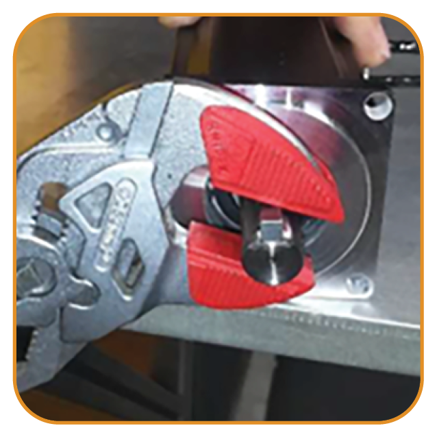
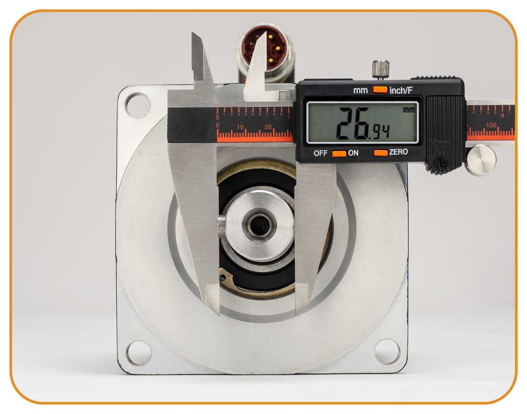
Figure 2: Example: Calipers measurement
|
|
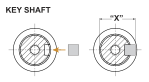
Shaft Height over key with Full Key Installed The height along the entire keyway length should fall within these tolerance ranges when installing the full key. (Figure 3)
|
||||||||
|
|
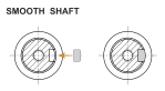
Shaft Diameter with Half/Modified Key Installed The modified key should align with the rounded surface of the shaft. (Figure 4)
See the individual |
||||||||
|
|
|