Recover Using the Web server
If the controller detects a problem in the firmware, the 7-segment display shows  .
.
This means a firmware recovery is needed.
The recovery modes are:
AKD PDMM and PCMM Web server Recovery
AKD PDMM and PCMM enter Recovery Mode automatically.
- Recovery Mode is used to select and upgrade a firmware image file containing the KAS Runtime image on the AKD PDMM or PCMM.
- When Recovery Mode cannot be automatically accessed, press and hold B2 at boot to force the AKD PDMM or PCMM to boot into Recovery Mode.
-
-
The Recovery Mode allows any firmware image file to be loaded into the controller's flash memory.
The Recovery Mode does NOT verify the selected firmware file is compatible with the hardware model.
Verify the Recommended File Name matches the selected firmware file.
If an incompatible firmware file is loaded into the AKD PDMM's or PCMM's flash memory, the AKD PDMM or PCMM fails to boot into the Runtime image and fails to automatically boot into Recovery Mode.
To recover from this situation requires manually booting into Recovery Mode.
See Boot from Recovery Image (B2 Button).
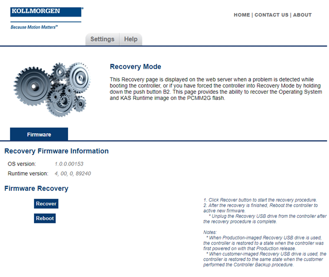
PCMM2G Web server Recovery
-
- Recovery Mode is not automatic for the PCMM2G.
Recovery USB Flash Drive
There are two kinds of Recovery USB drives:
Production Image Recovery Procedure
The Production-image Recovery USB flash drive is imaged using a production release using this procedure:
- Download and install the software from the balenaEtcher website.
- Download the PCMM2G recovery firmware wic.bz2 image file from the Kollmorgen Downloads page.
It is recommended to download the same version of the recovery image as the existing Operation System and Runtime image. - Open the balenaEtcher software.
- Use the balenaEtcher instructions to create the Recovery USB flash drive using the wic.bz2 file downloaded in Step 2.
- Insert the Recovery USB flash drive into X37 USB Port of the PCMM2G.
- Hold the B2 button and power-cycle the PCMM2G.
- Release the B2 button anytime after the 7-segment display shows
 .
.
See Booting the PCMM2G Controller.
If a 7-segment display appears while bootup with the B2 button held down, there is not a bootable drive inserted in the X37 USB Port.
 - When the PCMM2G is in Recovery Mode, connect to the controller from a web browser using it’s IP address (e.g., http://192.168.0.101).
- Click the Recover button on this web page to start the recovery procedure.

- Reboot the controller after the recovery is finished.
- Connect to the controller from the web browser and verify both the firmware OS and Runtime versions are as expected.
- Unplug the Recovery USB drive from the controller after the recovery procedure is completed.
- Production-image Recovery USB flash drive, you must reprogram the controller with your configuration.
- Customer-imaged Recovery USB flash drive, all settings are restored and the controller is fully operational.
See Recovery Operating System (OS) + KAS Runtime (RT) - File Naming Convention.
It is recommended to:
If you used the:
When using the Production-image Recovery USB flash drive to perform Recovery, the controller is restored to a state when the controller was powered on with that Production release.
Customer Image Recovery
The Customer-imaged backup Recovery USB flash drive is generated using the Controller Backup and Restore procedure.
-
- It is recommended to create the Recovery USB flash drive using the Controller Backup and Restore procedure every time the firmware on the controller is updated.
This procedure creates an exact backup of the controller unlike the Production-image Recovery USB flash drive.
This is an important difference while recovering the controller.
When using the customer-imaged Recovery USB flash drive to perform the Recovery, the controller is restored to the same state when the customer performed the Controller Backup procedure.
See Also


