AKT2G-AN-430-000
4-channel analog input, parameterizable, -10/0…+10 V, -20/0/+4…+20 mA, 16 bit
Jump to a section on this page:
See Also:
- Single-Ended / Differential Typification
- Dielectric strength
- Temporal Aspects of Analog/Digital Conversion
Related Topics: Map Input and Output to Variables
Configuration of 0/4..20 mA Differential Inputs
This section describes the 0/4..20 mA differential inputs for terminal series AKT2G-AN-430.
For the single-ended 20 mA inputs the terminal series AN-430 they only apply with regard to technical transferability and also for devices whose analog input channels have a common related ground potential (and therefore the channels are not to each other and/or not to power supply electrically isolated). Herewith an example for an electrically isolated device is the terminal AN-430.
Technical Background
The internal input electronics of the terminals referred to above have the following characteristic (see Figure 1: "Internal connection diagram 0/4...20 mA inputs"):
- Differential current measurement, i.e. concrete potential reference is primarily not required. The system limit applies is the individual terminal AN-430.
- Current measurement via a 33 Ω shunt per channel, resulting in a maximum voltage drop of 660 mV via the shunt
- Internal resistor configuration with GND point (A) central to the shunt
The configuration of the resistors is symmetric, such that the potential of (A) is central relative to the voltage drop via the shunt.
- All channels within the terminal have this GNDint potential in common.
- the common GNDint potential (A)
- is connected for 1 and 2 channel terminals to a terminal point and not with GNDPC (power contact).
- is connected for 4 channel terminals with GNDPC
- The center point of the voltage drop over the 33 Ω shunt is referred to common mode point (CMP). According to the technical product data, the maximum permitted UCM voltage (common mode) refers to the potential between the CMP of a channel and the internal GND or the potential between the CMP of 2 channels within a terminal.
It must not exceed the specified limit (typically ±10 or ±35 V).
Accordingly, for multi-channel measurements UCM specifications must be followed.
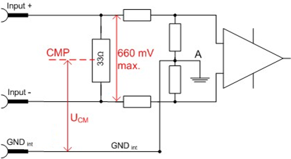
Figure 1: Internal connection diagram 0/4...20 mA inputs
The block diagram for a 2 channel terminal shows the linked GND points within the terminal (Internal connection diagram for 0/4..20 mA inputs of a AKT2G-AN-430):
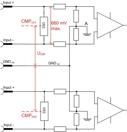
Figure 2: Internal connection diagram for 0/4..20 mA inputs of a AKT2G-AN-430
For all channels within the terminal UCM-max must not be exceeded.
-
-
UCM for 0/4..20 mA inputs
If UCM of an analog input channel is exceeded, internal equalizing currents result in erroneous measurements.
For 1 and 2 channel terminals the internal GND is therefore fed out to a terminal point, so that the UCM specification can be met through application-specific configuration of this GND point, even in cases of atypical sensor configuration.
Summary
- We recommended connecting GNDint with a low-impedance potential, because this significantly improves the measuring accuracy of the AN-430.
Please note the instructions relating to the UCM potential reference.
- The UCM potential reference must be adhered to between CMP ↔ GNDint and CMPch(x) ↔ CMPch(y).
If this cannot be guaranteed, the single-channel version should be used.
- Terminal configuration:
- AN-430: GND is connected with the negative power contact. The external connection should be such that condition 2 is met.
If the sensor cable is shielded, the shield should not be connected with the GNDint terminal point but with a dedicated low-impedance shield point.
- If terminal points of several AN-430 terminals are connected with each other, ensure that condition 2 is met.
-
-
Connection of GNDint
To achieve a precise measurement result GNDint should be connected to a suitable external low-impedance potential, taking account the specifications for UCM.
In the AN-430 terminals GNDint is already connected with the negative power contact. Here too the specifications for UCM must be followed.
CoE Object Description and Parameterization
Restore Object
|
Index (hex) |
Name |
Meaning |
Data type |
Flags |
Default |
|---|---|---|---|---|---|
|
1011:0 |
Restore default parameters |
Restore default parameters |
UINT8 |
RO |
0x01 (1dec) |
|
1011:01 |
SubIndex 001 |
If this object is set to “0x64616F6C” in the set value dialog, all backup objects are reset to their delivery state. |
UINT32 |
RW |
0x00000000 (0dec) |
Configuration Data
|
Index (hex) |
Name |
Meaning |
Data type |
Flags |
Default |
|---|---|---|---|---|---|
|
80n0:0 |
AI Settings |
Maximum subindex |
UINT8 |
RO |
0x18 (24dec) |
|
80n0:01 |
Enable user scale |
User scale is active. |
BOOLEAN |
RW |
0x00 (0dec) |
|
80n0:02 |
Presentation |
|
BIT3 |
RW |
0x00 (0dec) |
|
80n0:05 |
Siemens bits |
The S5 bits are displayed in the three low-order bits |
BOOLEAN |
RW |
0x00 (0dec) |
|
80n0:06 |
Enable filter |
Enable filter, which makes PLC-cycle-synchronous data exchange unnecessary |
BOOLEAN |
RW |
0x00 (0dec) |
|
80n0:07 |
Enable limit 1 |
Limit 1 enabled |
BOOLEAN |
RW |
0x00 (0dec) |
|
80n0:08 |
Enable limit 2 |
Limit 2 enabled |
BOOLEAN |
RW |
0x00 (0dec) |
|
80n0:0A |
Enable user calibration |
Enabling of the user calibration |
BOOLEAN |
RW |
0x00 (0dec) |
|
80n0:0B |
Enable vendor calibration |
Enabling of the vendor calibration |
BOOLEAN |
RW |
0x01 (1dec) |
|
80n0:0E |
Swap limit bits |
Changing of the Limit Bits |
BOOLEAN |
RW |
0x00 (0dec) |
|
80n0:11 |
User scale offset |
User scaling offset |
INT16 |
RW |
0x0000 (0dec) |
|
80n0:12 |
User scale gain |
User scaling gain. The gain is represented in fixed-point format, with the factor 2-16. The value 1 corresponds to 65536dec (0x00010000) and is limited to ±0x7FFFF |
INT32 |
RW |
0x00010000 (65536dec) |
|
80n0:13 |
Limit 1 |
First limit value for setting the status bits |
INT16 |
RW |
0x0000 (0dec) |
|
80n0:14 |
Limit 2 |
Second limit value for setting the status bits |
INT16 |
RW |
0x0000 (0dec) |
|
Filter settings |
This object determines the digital filter settings, if it is active via Enable filter (index 0x80n0:06). The possible settings are sequentially numbered.
|
UINT16 |
RW |
0x0000 (0dec) |
|
|
80n0:17 |
User calibration offset |
User offset compensation |
INT16 |
RW |
0x0000 (0dec) |
|
80n0:18 |
User calibration gain |
User calibration gain |
INT16 |
RW |
0x4000 (16384dec) |
-
-
The filter characteristics are set via index 0x8000:15 (see "80n0:15")
The filter frequencies are set for all channels of the AN-430 terminals centrally via index 0x8000:15 (channel 1). All other corresponding indices 0x80n0:15 have no parameterization function!
| Index (hex) | Name | Meaning | Data type | Flags | Default | |
|---|---|---|---|---|---|---|
|
80nD:0 |
AI Advanced Settings |
Maximum subindex |
UINT8 |
RO |
0x12 (18dec) |
|
|
80nD:11 |
Input Type |
Measurement mode, allowed values: |
UINT16 |
RW |
0x0002 (2dec) |
|
|
0x02 |
-10..+10 V |
|||||
|
0x0E |
0..10 V |
|||||
|
0x11 |
-20..+20 mA |
|||||
|
0x12 |
0..20 mA |
|||||
|
0x13 |
4..20 mA |
|||||
|
0x14 |
4..20 mA (NAMUR) |
|||||
|
80nD:12 |
Scaler |
Scaling range, allowed values: |
UINT16 |
RW |
0x0000 (0dec) |
|
|
0x00 |
Extended Range |
|||||
|
0x03 |
0x03 Legacy Range |
|||||
|
80nD:17 |
Low Range Error |
Lower threshold for setting the error bit and error led |
INT32 |
RW |
Dependent on 80nD:11 |
|
|
80nD:18 |
High Range Error |
Upper threshold for setting the error bit and error led |
INT32 |
RW |
Dependent on 80nD:11 |
|
|
Index (hex) |
Name |
Meaning |
Data type |
Flags |
Default |
|---|---|---|---|---|---|
|
80nE:0 |
AI internal data |
Maximum subindex |
UINT8 |
RO |
0x01 (1dec) |
|
80nE:01 |
ADC raw value |
ADC raw value |
UINT16 |
RO |
- |
|
Index (hex) |
Name |
Meaning |
Data type |
Flags |
Default |
|---|---|---|---|---|---|
|
80nF:0 |
AI vendor data |
Maximum subindex |
UINT8 |
RO |
0x02 (2dec) |
|
80nF:01 |
Calibration offset |
Offset (vendor calibration) |
INT16 |
RW |
0x0000 (0dec) |
|
80nF:02 |
Calibration gain |
Gain (vendor calibration) |
INT16 |
RW |
0x4000 (16384dec) |
|
Index (hex) |
Name |
Meaning |
Data type |
Flags |
Default |
|---|---|---|---|---|---|
|
80nF:0 |
AI Vendor data |
Maximum subindex |
UINT8 |
RO |
0x06 (6dec) |
|
80nF:01 |
R0 offset |
Offset (Vendor calibration) |
INT16 |
RW |
0x0000 (0dec) |
|
80nF:02 |
R0 gain |
Gain (Vendor calibration) |
INT16 |
RW |
0x4000 (16384dec) |
|
80nF:03 |
R1 offset |
Offset (Vendor calibration) |
INT16 |
RW |
0x0000 (0dec) |
|
80nF:04 |
R1 gain |
Gain (Vendor calibration) |
INT16 |
RW |
0x4000 (16384dec) |
|
80nF:05 |
R2 offset |
Offset (Vendor calibration) |
INT16 |
RW |
0x0000 (0dec) |
|
80nF:06 |
R2 gain |
Gain (Vendor calibration) |
INT16 |
RW |
0x4000 (16384dec) |
Input Data
|
Index (hex) |
Name |
Meaning |
Data type |
Flags |
Default |
|---|---|---|---|---|---|
|
60n0:0 |
AI inputs |
Maximum subindex |
INT16 |
RO |
0x11 (17dec) |
|
60n0:01 |
Underrange |
Value below measuring range. |
BOOLEAN |
RO |
0x00 (0dec) |
|
60n0:02 |
Overrange |
Measuring range exceeded. |
BOOLEAN |
RO |
0x00 (0dec) |
|
60n0:03 |
Limit 1 |
Limit value monitoring Limit 1
|
BIT2 |
RO |
0x00 (0dec) |
|
60n0:05 |
Limit 2 |
Limit value monitoring limit 2
|
BIT2 |
RO |
0x00 (0dec) |
|
60n0:07 |
Error |
The error bit is set if the data is invalid (over-range, under-range) |
BOOLEAN |
RO |
0x00 (0dec) |
|
60n0:0E |
Sync error |
The Sync error bit is only required for DC mode. It indicates whether a synchronization error has occurred during the previous cycle. This means a SYNC signal was triggered in the AN-430, although no new process data were available (0=OK, 1=NOK). |
BOOLEAN |
RO |
0x00 (0dec) |
|
60n0:0F |
TxPDO State |
Validity of the data of the associated TxPDO (0 = valid, 1 = invalid). |
BOOLEAN |
RO |
0x00 (0dec) |
|
60n0:10 |
TxPDO Toggle |
The TxPDO toggle is toggled by the slave when the data of the associated TxPDO is updated. |
BOOLEAN |
RO |
0x00 (0dec) |
|
60n0:11 |
Value |
Analog input date |
INT16 |
RO |
0x0000 (0dec) |
Technical Data
|
Technical Data |
AKT2G-AN-430-000 |
|
|---|---|---|
|
Analog inputs |
4 (U differential, I single-ended) |
|
|
Conversion type |
simultaneous |
|
|
ADC type |
SAR |
|
|
Signal voltage |
-10/0…+10 V |
|
|
Signal current |
-20/0/+4…+20 mA |
|
|
Measuring range, nominal (Full Scale Value) |
Voltage measurement range |
-10/0…+10 V |
|
Current measurement range |
-20/0/+4…+20 mA |
|
|
Measuring range, technical |
Voltage measurement range |
-10.73…+10.73 V |
|
Current measurement range |
-21.47…+21.47 mA |
|
|
Measuring error (full measuring range) |
< ±0.3 % (relative to full scale value) |
|
|
Distributed Clocks |
yes |
|
|
Distributed Clocks precision |
<< 1 µs |
|
|
Support NoCoeStorage |
yes |
|
|
Resolution |
16 bit (incl. sign) |
|
|
Internal resistance |
Voltage measurement: > 200 kΩ | Current measurement: 85 Ω typ. |
|
|
Input filter limit frequency |
5 kHz |
|
|
Common-mode voltage UCM |
35 V max. (voltage measurement) |
|
|
Minimal EtherCAT cycle time |
200 µs
|
|
|
Overcurrent protection |
50 mA typ. |
|
|
Bit width of the process image |
Inputs: 16 Byte
|
|
|
Configuration |
no address or configuration settings required |
|
|
MTBF (+55°C) |
-
|
|
|
Special features |
U/I parameterisable, Extended Range, standard and compact process image, activatable FIR/IIR filters |
|
|
Supply voltage for electronic |
via the E-bus |
|
|
Current consumption via E-bus |
typ. 170 mA |
|
|
Electrical isolation |
500 V (E bus/ fieldbus voltage) |
|
|
Recommended operating voltage range (ground related to GND/ 0V power contact) |
Voltage measurement range |
UCM 35 V max. |
|
Current measurement range |
single ended, dielectric strength max. 30 V |
|
|
Recommended signal range |
Voltage measurement range |
Extended Range (107%), differential |
|
Current measurement range |
Extended Range (107%), single ended |
|
|
Destruction limit (ground related to GND/ 0V power contact) |
Voltage measurement range |
50 V |
|
Current measurement range |
30 V |
|
|
Destruction limit (differential) |
Voltage measurement range |
50 V |
|
Current measurement range |
n.a. |
|
|
Weight |
approx. 65 g |
|
|
Permissible ambient temperature range during operation |
-25…+60 °C
|
|
|
Permissible ambient temperature range during storage |
-40…+85 °C
|
|
|
Permissible relative humidity |
95 %, no condensation |
|
|
Design |
HD (High Density) housing with signal LED |
|
|
Dimensions (W x H x D) |
approx. 15 mm x 100 mm x 70 mm (width aligned: 12 mm) |
|
|
Mounting |
on 35 mm mounting rail conforms to EN 60715 |
|
|
Vibration/shock resistance |
conforms to EN 60068-2-6/EN 60068-2-27 |
|
|
EMC immunity/emission |
conforms to EN 61000-6-2/EN 61000-6-4 |
|
|
Protection class |
IP20 |
|
|
Installation position |
variable |
|
|
Approval |
CE, cULus |
|