AKT2G-AT-410-000
Four-channel analog output terminals, 0..10 V, 12 bit
The AKT2G-AT-410 analog output terminal generates signals in the range between 0 and 10 V. The voltage is supplied to the process level with a resolution of 12 bits, and is electrically isolated. The output channels of the EtherCAT Terminal has a common ground potential. The output stages are powered by the 24 V supply. The signal state of the EtherCAT Terminals is indicated by light emitting diodes. The AT-410 supports distributed clocks, i.e. the input data can be monitored synchronously with other data that are also linked to distributed clock terminals. The accuracy across the system is < 100 ns.
Jump to a section on this page:
See Also:
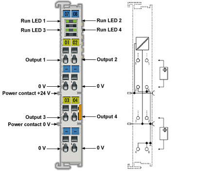
LEDs
|
LED |
Color |
Meaning |
|
|---|---|---|---|
|
RUN |
green |
This LED indicates the terminal's operating state: |
|
|
off |
State of the EtherCAT State Machine: INIT = initialization of the terminal, state of the EtherCAT State Machine: BOOTSTRAP = function for firmware updates of the terminal |
||
|
flashing |
State of the EtherCAT State Machine: PREOP = function for mailbox communication and different standard-settings set |
||
|
single flash |
State of the EtherCAT State Machine: SAFEOP = verification of the Sync Manager channels and the distributed clocks. Outputs remain in safe state |
||
|
on |
State of the EtherCAT State Machine: OP = normal operating state; mailbox and process data communication is possible |
||
If several RUN LEDs are present, all of them have the same function.
Object Description and Parameterization
Restore objects
|
Index (hex) |
Name |
Meaning |
Data type |
Flags |
Default |
|---|---|---|---|---|---|
|
1011:0 |
Restore default parameters |
Restore default parameters |
UINT8 |
RO |
0x01 (1dec) |
|
1011:01 |
SubIndex 001 |
If this object is set to “0x64616F6C” in the set value dialog, all backup objects are reset to their delivery state. |
UINT32 |
RW |
0x00000000 (0dec) |
Configuration data
|
Index (hex) |
Name |
Meaning |
Data type |
Flags |
Default |
|---|---|---|---|---|---|
|
8pp0:0 |
AO settings Ch.1-8 |
Max. Subindex |
UINT8 |
RO |
0x16 (22dec) |
|
8pp0:01 |
Enable user scale |
User scale is active. |
BOOLEAN |
RW |
0x00 (0dec) |
|
8pp0:02 |
Presentation |
|
BIT3 |
RW |
0x00 (0dec) |
|
8pp0:05 |
Watchdog |
0: Default watchdog value
|
BIT2 |
RW |
0x00 (0dec) |
|
8pp0:07 |
Enable user calibration |
Enable user calibration |
BOOLEAN |
RW |
0x00 (0dec) |
|
8pp0:08 |
Enable vendor calibration |
Enable vendor calibration |
BOOLEAN |
RW |
0x01 (1dec) |
|
8pp0:11 |
Offset |
User scaling offset |
INT16 |
RW |
0x0000 (0dec) |
|
8pp0:12 |
Gain |
User scaling gain. The gain is represented in fixed-point format, with the factor 2-16. The value 1 corresponds to 65535 (0x00010000). |
INT32 |
RW |
0x00010000 (65536dec) |
|
8pp0:13 |
Default output |
default output value |
INT16 |
RW |
0x0000 (0dec) |
|
8pp0:14 |
Default output ramp |
Ramp for ramping down to the default value Value in digits/ms. |
UINT16 |
RW |
0xFFFF (65535dec) |
|
8pp0:15 |
User calibration offset |
User calibration offset |
INT16 |
RW |
0x0000 (0dec) |
|
8pp0:16 |
User calibration gain |
User calibration gain |
UINT16 |
RW |
0xFFFF (65535dec) |
|
Index (hex) |
Name |
Meaning |
Data type |
Flags |
Default |
|---|---|---|---|---|---|
|
8ppE:0 |
AO internal data Ch.1-8 |
Max. Subindex |
UINT8 |
RO |
0x01 (1dec) |
|
8ppE:01 |
DAC raw value |
DAC raw value |
UINT16 |
RO |
0x0000 (0dec) |
|
Index (hex) |
Name |
Meaning |
Data type |
Flags |
Default |
|---|---|---|---|---|---|
|
8ppF:0 |
AO vendor data Ch.1-8 |
Max. Subindex |
UINT8 |
RO |
0x02 (2dec) |
|
8ppF:01 |
Calibration offset |
Vendor calibration offset |
INT16 |
RW |
0x0000 (0dec) |
|
8ppF:02 |
Calibration gain |
Vendor calibration gain |
UINT16 |
RW |
0x1EFA (7930dec) |
Output Data
|
Index (hex) |
Name |
Meaning |
Data type |
Flags |
Default |
|---|---|---|---|---|---|
|
7pp0:0 |
AO outputs Ch.1-8 |
Max. Subindex |
UINT8 |
RO |
0x01 (1dec) |
|
7pp0:01 |
Analog output |
Analog output data |
INT16 |
RO |
0x0000 (0dec) |
Technical Data
|
Technical Data |
AKT2G-AT-410-000 |
|---|---|
|
Number of outputs |
4 |
|
Power supply |
24 V DC via the power contacts |
|
Signal voltage |
0..10 V |
|
Load |
> 5 kΩ (short-circuit-proof) |
|
Measuring error |
< ± 0.1% (at 0 °C ... +55 °C, relative to the full scale value) < ± 0.2% (when the extended temperature range is used) |
|
Resolution |
12 bit |
|
Conversion time |
~ 250 µs |
|
Power supply for electronics |
via the E-bus |
|
Distributed Clocks |
yes |
|
Current consumption via Ebus |
typ. 140 mA |
|
Electrical isolation |
500 V (E-bus/field voltage) |
|
Bit width in process image |
4 x 16-bit AO output |
|
Configuration |
via KAS-IDE |
|
Weight |
approx. 60 g |
|
Permissible ambient temperature range during operation |
-25 °C ... +60 °C (extended temperature range) |
|
Permissible ambient temperature range during storage |
-40 °C ... +85 °C |
|
Permissible relative humid- ity |
95%, no condensation |
|
Dimensions (W x H x D) |
approx. 15 mm x 100 mm x 70 mm (width aligned: 12 mm) |
|
Mounting |
on 35 mm mounting rail conforms to EN 60715 |
|
Vibration/shock resistance |
conforms to EN 60068-2-6 / EN 60068-2-27, see also installation instructions for enhanced mechanical load capacity |
|
EMC immunity/emission |
conforms to EN 61000-6-2 / EN 61000-6-4 |
|
Protection class |
IP20 |
|
Installation position |
variable |
|
Approval |
CE, ATEX, cULus |