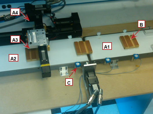
A1 - Feed Conveyor
A2 - Cut Conveyor
A3 - "Knife"
A4 - Sync
B - Product
This Flying Knife Application Module details sample code for a 4 axis system.
A1 - Feed Conveyor – Feeds material from upstream operation.
A2 - Cut Conveyor – Material flows from the feed conveyor to the cut conveyor. On the cut conveyor the material is cut by a flying knife (A3).
A3 - Knife – Move the knife through the material once the Sync axis is in synchronization with the sync axis. The knife is mounted on a linear actuatorA mechanical device for moving or controlling a mechanism or system. An actuator typically is a mechanical device which transforms an input signal (usually an electrical signal) into motion
A4 - Sync - Holds the cutting mechanism and ramps up to be in sync with the A2 conveyor. The sync axis is a linear actuator.
Used in this application Module:
A mechanical flying knife simulator was built up to demonstrate and test this motion. Flying knife cutting was simulated by running a wire connected to the A3- Knife axis through a slot in the product moving down the A2 cut conveyor.
|
|
A1 - Feed Conveyor A2 - Cut Conveyor A3 - "Knife" A4 - Sync B - Product |
The program code provided with this application module is contained in two programs that can be imported into a project: FlyingKnife_AutoMode.xk5 and FlyingKnife_ManualMode.xk5.
Key FunctionA function calculates a result according to the current value of its inputs. A function has no internal data and is not linked to declared instances. Blocks and Kollmorgen UDFBs used in the application:
| Name | How Used | Program |
|---|---|---|
|
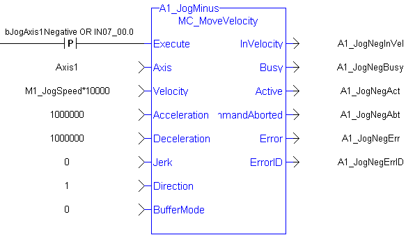
MC_MoveVelocity |
Jog the axes |
FlyingKnife_ManualMode |
|
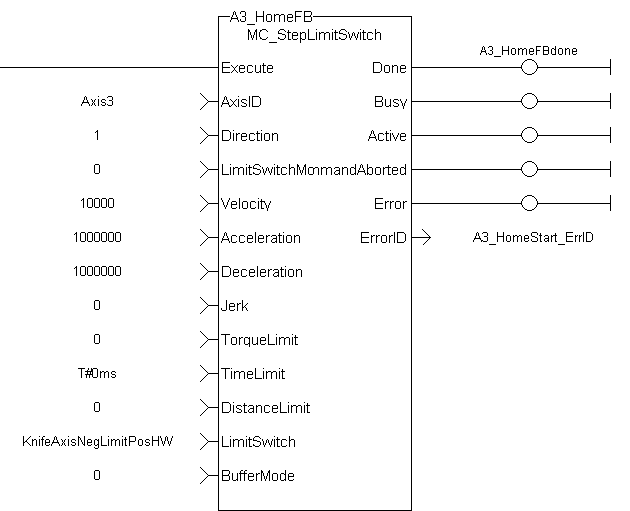
MC_StepLimitSwitch |
Home the axis |
FlyingKnife_ManualMode |
|
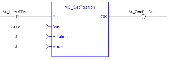
MC_SetPosition |
Set a motor/load position after homing |
FlyingKnife_ManualMode |
|
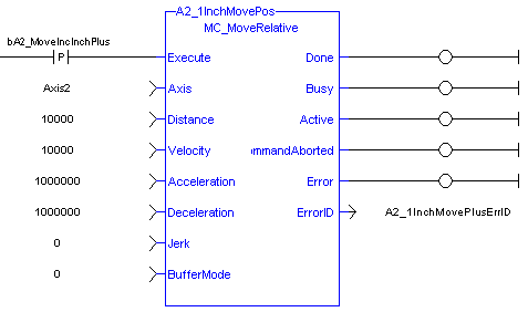
MC_MoveRelative |
Make a relative move |
FlyingKnife_ManualMode |
|
MC_Gearin |
Synchronize the A2 cut conveyor to the feed conveyor |
FlyingKnife_AutoMode |
|
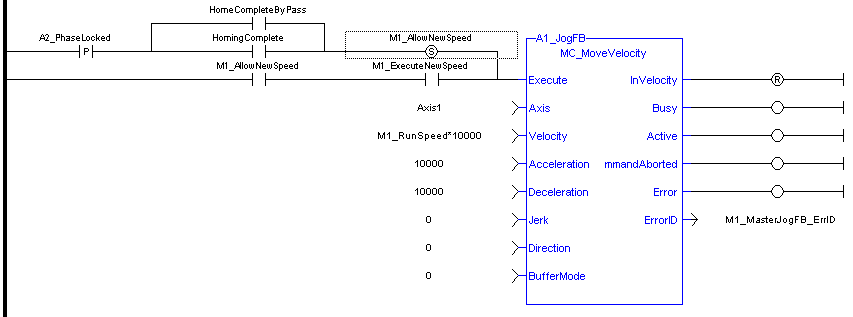
MC_MoveVelocity |
Sets the speed of the A1 feed and A2 cut conveyors |
FlyingKnife_AutoMode |
|
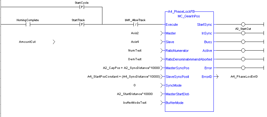
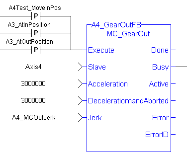
MC_GearInPos |
Synchronizes the A4 sync mechanism to the A2 cut conveyor |
FlyingKnife_AutoMode |
|
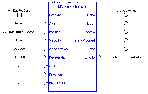
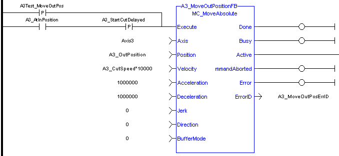
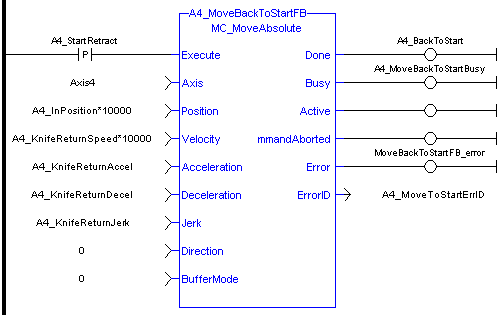
MC_MoveAbsolute |
Move the A3 knife through the material, Move A4 sync axis back to the start position after the cut is made |
FlyingKnife_AutoMode |
|
ECATWriteSdo |
Setup the high speed trigger to sense next work piece coming through the machine |
FlyingKnife_AutoMode |
|
MC_TouchProbe |
Capture position of A2 cut conveyor when material is sensed |
FlyingKnife_AutoMode |
|
Trigger_REF |
Library function used to execute high speed position capture |
FlyingKnife_AutoMode |
In manual operation mode the sync and cut axes are homed. All 4 axes can be jogged in each direction as well as an incremental move can be made.
Jogging
HomingThe Homing procedure allows, based on a position measurement, to set a position offset to the motor in order to ensure it is physically at the home position for the A3 Knife and A4 Sync Axes only is accomplished using an end of travel switch limit switch. The limit switch is connected to the drive. The MC_StepLimitSwitch FB is used for this.
Once at the home position the MC_SetPosition function establishes the axes position:
The axis is then moved to the flying knife’s starting position mechanism by performing an absolute move:
Also in the manual program are FBs to perform incremental motion using the MC_MoveRelative FB:
The automatic operation mode program includes the following sections of code:
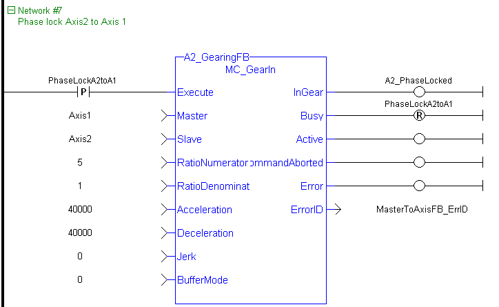
SlaveCommandPosition = MasterActualPosition * RatioNumerator / RatioDenominator
This function block also allows the application to specify sync positions, the point in which the master and slave axes become engaged in synchronous motion, for the master and slave axes. When the master axis (A2- cut conveyor) reaches the MasterStartDistance from the MasterSyncPosition, the slave axis (A4 sync) begins to accelerate to the target velocity determined by the master axis velocity and the ratio. The A4 Sync axis arrives at the target velocity and the A4 SyncPosition at the same time the A2 cut conveyor arrives at the A2 SyncPosition. At that time, the A4 sync is locked on to the A2 cut conveyor and follows it at the ratio specified until this move is aborted using the MC_GearOut FB. In physics, jerkIn physics, jerk is the rate of change of acceleration; more precisely, the derivative of acceleration with respect to time is the rate of change of acceleration; more precisely, the derivative of acceleration with respect to time
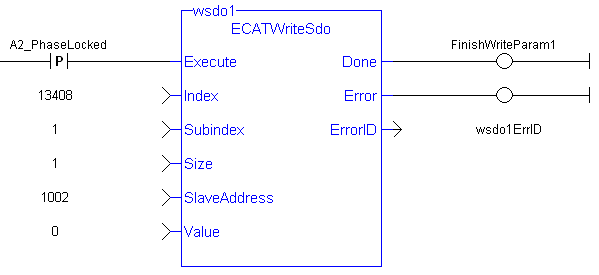
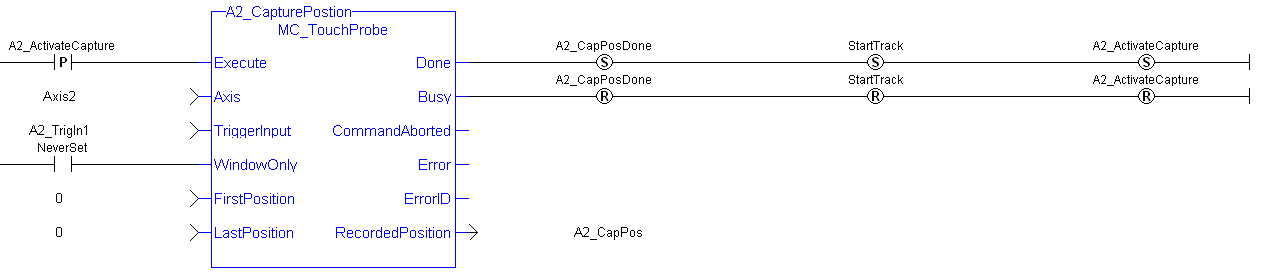
The captured position is sent to the controller through the high performance EtherCATEtherCAT is an open, high-performance Ethernet-based fieldbus system. The development goal of EtherCAT was to apply Ethernet to automation applications which require short data update times (also called cycle times) with low communication jitter (for synchronization purposes) and low hardware costs interface.
The application also contains an out of tolerance input from one of the drives general purpose inputs. The number of Out of tolerance cuts are keep track of by the program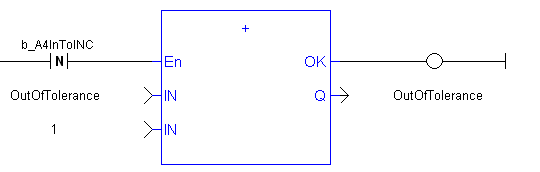
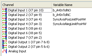
A3 Cut Axis – End of travel switches, also used for in homing:
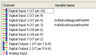
A4 Sync Axis - End of travel switches, also used for in homing plus cut in-tolerance and out-of-tolerance inputs:
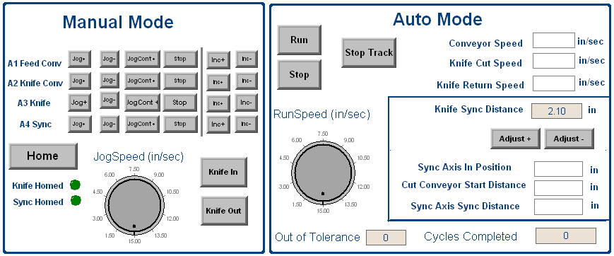
In the Manual and Auto files is code to support the following control panel:
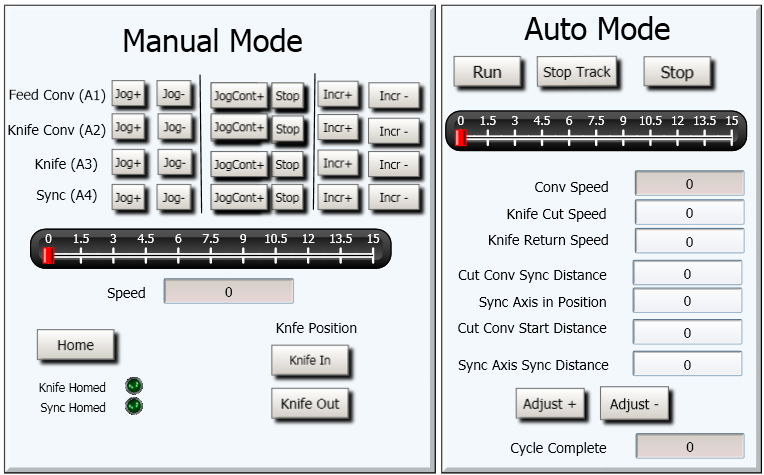
A KVB panel was also created:
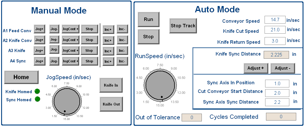
The following parameters are one example of running the modules. Note: the max production rate was limited by the ball screw actuator and motor on the A4 sync axis. Faster rates are possible by using another type of actuator such as a linear motor or belt and pulley type actuator.
|
Stay Connected with Kollmorgen       
|
Copyright © 2015 Kollmorgen™ |

|