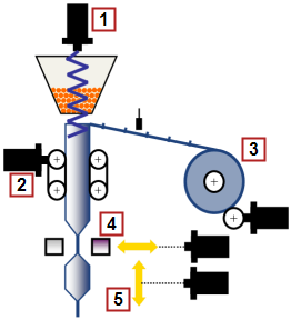
- Filling Screw (via cam)
- Film transport unit to RM
- Unwinding
- Sealing jaw
- Flying Shear
This application module details a 5 axis form, fill, and seal machine (FFS) using the Pipe Network motion engine. The unwind axis maintains a desired tension on the film as the film transport; using registration marks on the film; positions the film. When in position the filling screw fills the bag, the sealing jaw will seal the bag, and the flying shear will cut on the seal to provide each individually formed, filled, and sealed bag.
|
|
|
Figure 11-220: Form Fill and Seal Machine Overview
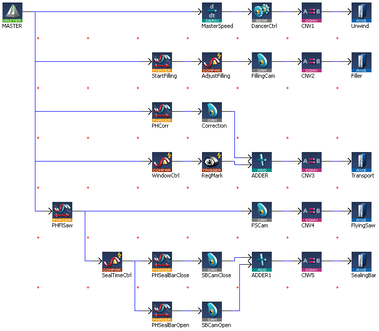
The combination of pipeblocks and PLC"Programmable Logic Controller" A Programmable Logic Controller, PLC, or Programmable Controller is a digital computer used for automation of industrial processes, such as control of machinery on factory assembly lines. Used to synchronize the flow of inputs from (physical) sensors and events with the flow of outputs to actuators and events code can easily be modified for use in a variety of form fill and seal applications, by modifying the CAM profiles and machine cycle times to fit machines with varying mechanics and desired material cut lengths.
The unwind axis is geared to the virtual master axis. As the film is being unwound from the parent roll a dancer roll is monitoring the desired tension. If the tension is outside the desired adjustable dead band the gear ratio between the virtual master axis and unwind is adjusted to maintain the desired tension. The tension (Regulation TnIntegral component of a control loop), gain to control the tension (Regulation KpProportional gain of a control loop), minimum and maximum dead band (Min Deadband & max Deadband) is entered on the control panel.
The filling axis is geared to the master virtual axis based on a profile (FillingPro). The phase shift, speed, and quantity variables for the filling screw are entered on the operator panel. The phase shift is the position on the master axis that the filling axis profile (FillingPro) will start. The speed is the time from the start position to a point in the master position that the filling screw profile follows the master. The quantity is the amount of the “FillingPro” profile to be executed.
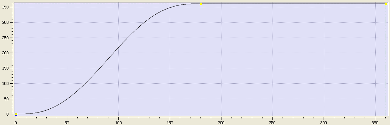
Figure 11-221: Filling Screw Base Profile
The film transport axis monitors the registration marks on the film and adjusts the film based on the registration mark parameters, Open Window, Close Window, and Reference Pos entered on the operator panel. If the registration mark is detected between the Open Window and Close Window the registration mark is considered a good mark and the Reference Pos value will be used to calculate the necessary adjustment. If the registration mark is detected outside the Open Window and Close Window values then the registration mark is ignored. Adjustments are not made during the seal process to avoid destroying product.
The sealing jaw axis is geared to the master virtual axis based on two profiles (SealBarClose and SealBaropen). The profile will start at the same starting position as the flying shear. The sealing time is entered at the operator interface.
Figure 11-222: Sealing Jaw Base Profile
The flying shear axis is geared to the master virtual axis based on a profile (FlySaw). The profile will start at the phaseshift entered at the operator interface.
Figure 11-223: Flying Shear Base Profile
Key FunctionA function calculates a result according to the current value of its inputs. A function has no internal data and is not linked to declared instances. Blocks and Kollmorgen UDFBs used in the application
| Name | How Used |
|---|---|
|
MC_GearIn |
Gears one axis to another |
|
MC_CamIn |
Gears one axis to another using a cam profile |
|
MC_TouchProbe |
The main section of the PLC code contains several If/Then statements. The program sets up gearing and cam profiles for the slave axis to a virtual master. The virtual master controls the machine speed. The slave axes are manipulated by either changing the operator panel inputs or profiles. The program is monitoring registration marks on the film and making correction to the film position based on the entries at the operator panel.
//****************
// MachineThe complete assembly of all connected parts or devices, of which at least one is movable Control
//****************
IF bStart THEN
fStart(bStart);
IF OldMachineSpeed<>MachineSpeed THEN
MLMstRun(PipeNetwork.MASTER, MachineSpeed);
OldMachineSpeed:=MachineSpeed;
END_IF;
ELSE
IF fStart.Q THEN
MLMstWriteSpeed(PipeNetwork.MASTER, MachineSpeed);
MLMstAbs(PipeNetwork.MASTER, 720.0);
OldMachineSpeed:=0.0;
END_IF;
END_IF;
//***************
// Dancer Control
//***************
// Range 0-10V, 5V mid, 4-6V Deadband, <4V increase speed, >6V decrease speed
IF bStart THEN
IF (AnaInDancer<MinDeadBand) THEN
DancerGear:=(AnaInDancer-DancerRef)*Kp;
IF Tn>0.0 THEN
DancerGearI:=OldDancerGearI+(AnaInDancer-DancerRef)*Kp/Tn*1000;
OldDancerGearI := DancerGearI;
ELSE
DancerGearI := 0.0;
OldDancerGearI := 0.0;
END_IF;
DancerGear := DancerGear+DancerGearI;
IF DancerGear > LREAL#1.0 THEN
DancerGear:=LREAL#1.0;
OldDancerGearI := LREAL#1.0;
ELSIF DancerGear < LREAL#-1.0 THEN
DancerGear:=LREAL#-1.0;
OldDancerGearI := LREAL#-1.0;
END_IF;
OldDancerGear:=DancerGear;
MLGearWriteRatio(PipeNetwork.DancerCtrl, (LREAL#1.0+DancerGear));
ELSIF (AnaInDancer>MaxDeadBand) THEN
DancerGear:=(AnaInDancer-DancerRef)*Kp;
IF Tn>0.0 THEN
DancerGearI:=OldDancerGearI+(AnaInDancer-DancerRef)*Kp/Tn*1000;
OldDancerGearI := DancerGearI;
ELSE
DancerGearI := 0.0;
OldDancerGearI := 0.0;
END_IF;
DancerGear := DancerGear+DancerGearI;
IF DancerGear > LREAL#1.0 THEN
DancerGear:=LREAL#1.0;
OldDancerGearI := 1.0;
ELSIF DancerGear < LREAL#-1.0 THEN
DancerGear:=LREAL#-1.0;
OldDancerGearI := LREAL#-1.0;
END_IF;
OldDancerGear:=DancerGear;
MLGearWriteRatio(PipeNetwork.DancerCtrl, (LREAL#1.0+DancerGear));
ELSE
// Deadband
END_IF;
END_IF;
//*************
// Filling axis
//*************
IF MLCompCheck(PipeNetwork.AdjustFilling) THEN
MLCompReset(PipeNetwork.AdjustFilling);
MLPhaWritePhase(PipeNetwork.StartFilling,PhaseFilling);
MLPrfWriteIScale(Profiles.FillingPro,IRatioFilling);
MLPrfWriteOScale(Profiles.FillingPro,ORatioFilling);
END_IF;
//*****************************************
// Transport axis with registration control
//*****************************************
IF MLCompCheck(PipeNetwork.WindowCtrl) THEN
IF bWindowOpen THEN
MLCompWriteRef(PipeNetwork.WindowCtrl, (OpenWindow<MLBlkReadOutVal(PipeNetwork.WindowCtrl)), OpenWindow);
MLCompReset(PipeNetwork.WindowCtrl);
bWindowOpen:=FALSE;
IF MLTrigIsTrigged(PipeNetwork.RegMark) THEN
CorrLength:=MLTrigReadPos(PipeNetwork.RegMark)-ReferencePos;
IF CorrLength>MaxCorrLength THEN
CorrLength:=MaxCorrLength;
ELSIF CorrLength< -MaxCorrLength THEN
CorrLength:=-MaxCorrLength;
END_IF;
ELSE
CorrLength:=MaxCorrLength;
END_IF;
MLPhaWritePhase(PipeNetwork.PHCorr,LREAL#-1.0*CloseWindow);
MLPrfWriteOScale(Profiles.Corr, CorrLength);
ELSE
MLCompWriteRef(PipeNetwork.WindowCtrl, (CloseWindow<MLBlkReadOutVal(PipeNetwork.WindowCtrl)), CloseWindow);
MLCompReset(PipeNetwork.WindowCtrl);
bWindowOpen:=TRUE;
MLTrigClearFlag(PipeNetwork.RegMark);
MLAxisRstFastIn(PipeNetwork.Transport, 0);
END_IF;
END_IF;
//**********
// Flying saw
//**********
IF PhaseFlySaw <> OldPhaseFlySaw THEN
MLPhaWritePhase(PipeNetwork.PHFlSaw,PhaseFlySaw);
OldPhaseFlySaw := PhaseFlySaw;
END_IF;
//************
// Sealing bar
//************
IF MLCompCheck(PipeNetwork.SealTimeCtrl) THEN
MLCompReset(PipeNetwork.SealTimeCtrl);
MLPhaWritePhase(PipeNetwork.PHSealBarOpen,LREAL#-270.0);
IF bStart THEN
bStartSealTimer := TRUE;
END_IF;
END_IF;
TimerSealing(bStartSealTimer,SealTime);
IF TimerSealing.Q THEN
bStartSealTimer := FALSE;
MLPhaWritePhase(PipeNetwork.PHSealBarOpen,LREAL#-1.0*MLBlkReadOutVal(PipeNetwork.SealTimeCtrl));
MLPrfWriteOScale(Profiles.SealBarOpen,360.0);
MLPrfWriteOOffset(Profiles.SealBarOpen,LREAL#-90.0);
END_IF;
//******************
// ResetNew start of the microprocessor axis errors
//******************
IF bReset THEN
MLAxisClrErrors(PipeNetwork.Unwind);
MLAxisClrErrors(PipeNetwork.Filler);
MLAxisClrErrors(PipeNetwork.Transport);
MLAxisClrErrors(PipeNetwork.FlyingSaw);
MLAxisClrErrors(PipeNetwork.SealingBar);
bReset := FALSE;
END_IF;
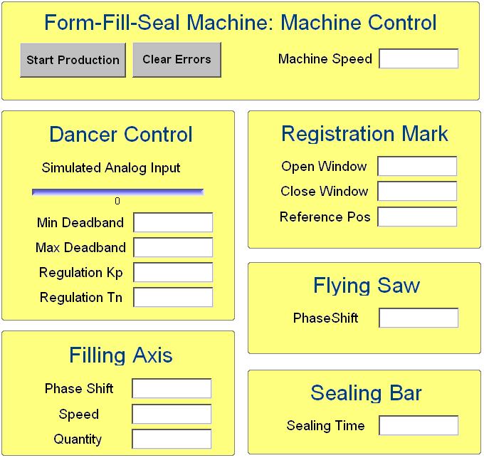
The Kollmorgen Automation Suite (KAS) program for this application module has an internal operator panel. The operator panel is used to set the desired values for each product and to start and stop the machine. The specific entries are described in the axis sections above. Below is a screen print of the operator panel.
|
Stay Connected with Kollmorgen       
|
Copyright © 2015 Kollmorgen™ |

|