 FB_PWDutyOutput FB_PWDutyOutput
The PulseWhen the step gets activated, the action is activated for a single execution, and possibly once again when the step is deactivated Width Duty Cycle function block accepts an input value between the minimum and maximum input range and converts this to a duty cycle percentage. The output is then cycled on and off over the period of the duty cycle at the duty cycle percentage. If it is desired to have the output ON time range from 0 to the duty cycle period, the minimum should be set to zero and the maximum to the duty cycle period. If the calculated duty cycle based on the input and range values is less than the minimum ON time (MinTime), the output will not come on. If the calculated duty cycle is between or equal to the range values the output is cycled by the duty cycle. If the calculated duty cycle is greater than the maximum ON time (MaxTime) the output will remain on.
The following figure shows the function block I/O
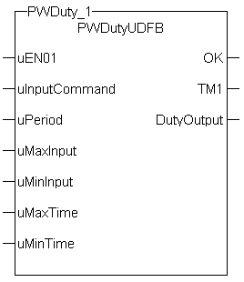
Figure 11-194: Pulse Width Duty Cycle
|
uEN01 |
Description |
|
|
Data type |
BOOL |
|
|
Range |
[0 , 1] |
|
|
Unit |
n/a |
|
|
Default |
— |
|
uInputCommand |
Description |
Duty Cycle Input (sometimes the output of a PID"Proportional-Integral-Derivative" A PID controller is a generic control-loop feedback mechanism widely used in industrial control systems. An "error" occurs when an event or a disturbance triggers off a change in the process variable. A PID controller attempts to correct the error between a measured process variable and a desired setpoint by calculating and then outputting a corrective action that can adjust the process accordingly block). |
|
Data type |
REAL |
|
|
Range |
[0 , 1] |
|
|
Unit |
n/a |
|
|
Default |
— |
|
uPeriod |
Description |
Period of the duty cycle |
|
Data type |
||
|
Range |
[0 , 1] |
|
|
Unit |
n/a |
|
|
Default |
— |
|
uMaxInput |
Description |
Maximum value for the Input |
|
Data type |
REAL |
|
|
Range |
[0 , 1] |
|
|
Unit |
n/a |
|
|
Default |
— |
|
uMinInput |
Description |
Minimum value for the Input |
|
Data type |
REAL |
|
|
Range |
[0 , 1] |
|
|
Unit |
n/a |
|
|
Default |
— |
|
uMaxTime |
Description |
Maximum on time for the Output |
|
Data type |
||
|
Range |
[0 , 1] |
|
|
Unit |
n/a |
|
|
Default |
— |
|
uMinTime |
Description |
Minimum on time for the Output |
|
Data type |
||
|
Range |
[0 , 1] |
|
|
Unit |
n/a |
|
|
Default |
— |
|
OK |
Description |
|
|
Data type |
BOOL |
|
|
Unit |
n/a |
|
TM1 |
Description |
Duty cycle on time |
|
Data type |
||
|
Unit |
n/a |
|
DutyOutput |
Description |
Indicates if output is on or off |
|
Data type |
BOOL |
|
|
Unit |
n/a |
Flash a warning light for operators.
|
Inst_FB_PWDutyOutput( PWDuty_3_Switch, PWDuty_In3, PWDuty_3_Period, PWDuty_3_MaxInput, PWDuty_3_MinInput, PWDuty_3_MaxTime, PWDuty_3_MinTime); PWDuty_3_OK:=Inst_FB_PWDutyOutput.OK; PWDuty_3_Time:=Inst_FB_PWDutyOutput.TM1; PWDuty_3_Output:=Inst_FB_PWDutyOutput.DutyOutput;
|
|
Stay Connected with Kollmorgen       
|
Copyright © 2015 Kollmorgen™ |

|
 [Top]
[Top]