 MC_MachRegistMC_MachRegist
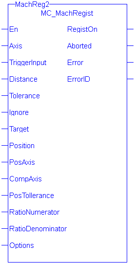
This function block enables Mark-to-MachineThe complete assembly of all connected parts or devices, of which at least one is movable registration and can be used on any servo or digitizing axis and with any move type. It is most frequently used in master/slave applications.
| En | Description | Rising edge of EN enables execution |
| Data type |
BOOL |
|
| Range |
0, 1 |
|
| Unit |
n/a |
|
| Default |
— |
|
| Axis | Description | Axis whose position is used to determine a good mark. |
| Data type | Axis_Ref | |
| Range | The range of .AXIS_NUM is [1,256] | |
| Unit | n/a | |
| Default | n/a | |
| TriggerInput | Description |
Structure specifying the fast input. The structure elements are: 0 = Capture Engine 0 1 = Capture Engine 1 Range is [0,1] For information on configuring the capture engines, refer to AKD Capture Engine Configuration. Direction INT TrigID INT
|
| Data type | TRIGGER_REF | |
| Range | ||
| Unit | ||
| Default | ||
| Distance | Description | This is the expected distance between good marks. Along with Tolerance and Ignore, this value is used to determine if the mark detected by the fast input is a good mark. |
| Data type | LREAL | |
| Range | When converted to feedback units, the range is [-251,251-1]. This value must have the same sign as Ignore. | |
| Unit | user units | |
| Default | n/a | |
| Tolerance | Description | This value specifies the distance, plus or minus, about Distance to determine if the mark detected by the fast input is a good mark. |
| Data type | LREAL | |
| Range | When converted to feedback units, the range is [0 ,251-1] | |
| Unit | user units | |
| Default | n/a | |
| Ignore | Description | This value specifies the distance after the previous good mark in which any detected marks are ignored. |
| Data type | LREAL | |
| Range | When converted to feedback units, the range is [-251,251-1]. This value must have the same sign as Distance. | |
| Unit | user units | |
| Default | n/a | |
| Target | Description | This is the target position. This position is compared to the actual position captured by the fast input to determine the amount of registration compensation to apply. |
| Data type | LREAL | |
| Range | When converted to feedback units, the range is:
|
|
| Unit | user units | |
| Default | n/a | |
| Position | Description | The position the axis is set to when a good registration mark occurs. If the “Inhibit Reference on Good Mark” option is specified for the Option argument (see Options Table below), then this argument is not used and the position of the axis is not changed when a registration mark is encountered. |
| Data type | LREAL | |
| Range | When converted to feedback units, the range is:
|
|
| Unit | user units | |
| Default | n/a | |
| PosAxis | Description | The position of this axis at the time the fast input occurs is compared to the Target position to determine the amount of registration compensation to apply. |
| Data type | AXIS_REF | |
| Range | The range of .AXIS_NUM is [1,256] | |
| Unit | n/a | |
| Default | n/a | |
| CompAxis | Description | The calculated registration compensation is applied to this axis. |
| Data type | AXIS_REF | |
| Range | The range of .AXIS_NUM is [1,256] | |
| Unit | n/a | |
| Default | n/a | |
| PosTolerance | Description | This value specifies the distance, plus or minus, about the Target position to determine if the position will be accepted and compensation value is calculated and applied. |
| Data type | LREAL | |
| Range | When converted to feedback units, the range is [-251,251-1] | |
| Unit | user units | |
| Default | n/a | |
| RatioNumerator | Description | This value is typically the number of User Units of CompAxis motion for one product cycle. This value is used with RatioDenominator to create a conversion factor for calculating the compensation value when PosAxis and CompAxis are different axes. |
| Data type | DINT | |
| Range | When converted to feedback units, the range is [1,4294967295] | |
| Unit | user units | |
| Default | n/a | |
| RatioDenominator | Description | This value is typically the number of User Units of PosAxis motion for one product cycle. This value is used with RatioNumerator to create a conversion factor for calculating the compensation value when PosAxis and CompAxis are different axes. |
| Data type | DINT | |
| Range | When converted to feedback units, the range is [1,4294967295] | |
| Unit | user units | |
| Default | n/a | |
| Options | Description | Each bit enables/disables an option. The following table defines the bits. Any bits not defined are reserved. The third bit, 0004H, must be 0. |
| Data type | UINT | |
| Range | refer to the following options table | |
| Unit | n/a | |
| Default | n/a |
| Hexadecimal | Decimal | Option | Description |
|---|---|---|---|
| 0001 H | 1 | Absolute/Resetting | 0 = Resetting, 1 = Absolute |
| 0002 H | 2 | Reserved | 0 |
| 0004 H | 4 | Time/position based capture | 0 = time based capture, 1 = position based capture |
| 0008 H | 8 | Inhibit Reference on Good Mark | 0 = Perform reference, 1 = inhibit reference When this bit is set, the Position function block argument is unused and the axis position is not changed when a registration mark is encountered. |
| 0010H | 16 | Inhibit Master Compensation | 0 = Perform Master Compensation, 1 = Inhibit Master Compensation |
| 0020H | 32 | Inhibit Slave Compensation | 0 = Perform Slave Compensation, 1 = Inhibit Slave Compensation. |
Table 11-44: MC_MachRegist Options Table
| RegistOn | Description |
Indicates registration is activated |
| Data type |
BOOL |
|
| Aborted | Description | Indicates registration has been terminated by MC_StopRegist. |
|
|
Data type | BOOL |
| Error | Description | Indicates an invalid input was specified or registration was terminated due to an error |
|
|
Data type | BOOL |
| ErrorID | Description | Indicates the error if Error output is TRUE. See table in PLCopen Function Block ErrorID Output. |
|
|
Data type | INT |
To use Capture Engine 1 modify the input PDOs that are used and add the LatchThe control word is used to activate the drive's latch status machine. The latch control word is processed independently of the EtherCAT bus cycle. The status word is used to return the drive's latch status Position 1 parameter.


|
Stay Connected with Kollmorgen       
|
Copyright © 2015 Kollmorgen™ |

|
 [Top]
[Top]