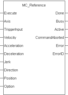
 MC_ReferenceMC_Reference
At this time, position capture is not available for PLCopenA vendor -and product- independent worldwide association active in Industrial Control and aiming at standardizing PLC file formats based on XML axes assigned to the secondary feedback input (digitizing axes). Therefore, MC_Reference cannot be used to home digitizing axes at this time.
When using position-based capture, the proper Capture Mode and FB Source may need to be set up in the drive. One place to do that is in the Position Capture Screen in the KAS IDE"Integrated development environment"
An integrated development environment is a type of computer software that assists computer programmers in developing software.
IDEs normally consist of a source code editor, a compiler and/or interpreter, build-automation tools, and a debugger embedded WorkBench: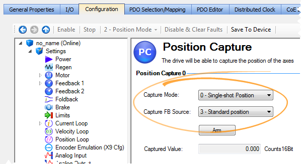
When setting up Position Capture, check the CoE-Init Command settings shown below. This is to verify they do not overwrite the corresponding drive parameters with unwanted values when the EtherCATEtherCAT is an open, high-performance Ethernet-based fieldbus system. The development goal of EtherCAT was to apply Ethernet to automation applications which require short data update times (also called cycle times) with low communication jitter (for synchronization purposes) and low hardware costs network initializes.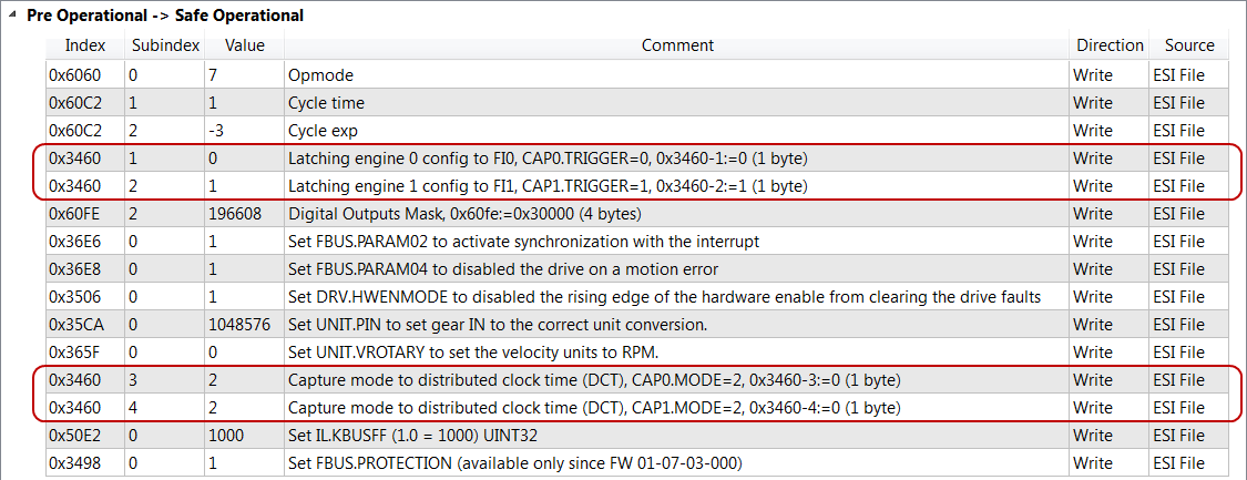
For more detail on how inputs and outputs work, refer to PLCopen Function Blocks - General Rules
| Execute | Description | Requests to queue the MC_Reference move and arms reference trigger events |
| Data type | BOOL | |
| Range | 0, 1 | |
| Unit | n/a | |
| Default | — | |
|
Axis |
Description |
Name of a declared instance of the AXIS_REF library function. For more details,About Axis Name and Number) |
| Data type | ||
| Range |
[1,256] |
|
| Unit |
n/a |
|
| Default |
— |
|
|
TriggerInput |
Description |
TRIGGER_REF structure defines the trigger InputID INT : 0 = Capture Engine 0 1 = Capture Engine 1 Range is [0,1] For information on configuring the capture engines, refer to AKD Capture Engine Configuration. Direction INT; 1 = rising edgeA rising edge is the transition of a digital signal from low to high. It is also called positive edge of trigger, 2 = falling edge of trigger Trigid INT; must be zero
|
| Data type |
TRIGGER_REF |
|
| Range |
See Description above |
|
| Unit |
n/a |
|
| Default |
— |
|
|
Velocity |
Description |
Commanded velocity for the reference move |
| Data type |
LREAL |
|
| Range |
— |
|
| Unit |
User unit/sec |
|
| Default |
— |
|
| Acceleration | Description | Commanded acceleration for the reference move |
| Data type | LREAL | |
| Range | — | |
| Unit | User unit/sec2 | |
| Default | — | |
| Deceleration | Description | Commanded deceleration for the reference move |
| Data type | LREAL | |
| Range | — | |
| Unit | User unit/sec2 | |
| Default | — | |
| JerkIn physics, jerk is the rate of change of acceleration; more precisely, the derivative of acceleration with respect to time | Description | Commanded jerkIn physics, jerk is the rate of change of acceleration; more precisely, the derivative of acceleration with respect to time for the reference move (if zero, then trapezoidal acc/dec is used) |
| Data type | LREAL | |
| Range | — | |
| Unit | User unit/sec3 | |
| Default | — | |
| Direction | Description | Commanded Direction of the reference |
| Data type | SINT | |
| Range | [0,1] | |
| Unit | n/a | |
| Default | — | |
| Position | Description | The position the axis will be reset to when at the machine reference location |
| Data type | LREAL | |
| Range | — | |
| Unit | User unit | |
| Default | — | |
| Option | Description |
Option identifier for Resolvers/Modulo reference. 0 = Use latched position for reference 1 = use resolver position of nearest null for reference 2 pole resolver 2 = use resolver position of nearest null for reference 4 pole resolver 3 = use resolver position of nearest null for reference 6 pole resolver 4 = use resolver position of nearest null for reference 8 pole resolver 5 = use resolver position of nearest null for reference 10 pole resolver … 15 = use resolver position of nearest null for reference 30 pole resolver |
| Data type | SINT | |
| Range | [0,15] | |
| Unit | n/a | |
| Default | — |
| Done | Description | Indicates the reference move and position adjustment is complete |
| Data type | BOOL | |
| Busy | Description | Indicates this function block is executing |
| Data type | BOOL | |
| Active | Description | Indicates this move is the Active move |
| Data type | BOOL | |
| CommandAborted | Description | Indicates the move was aborted |
| Data type | BOOL | |
| Error | Description | Indicates an invalid input, or the move was terminated due to an error |
| Data type | BOOL | |
| ErrorID | Description |
Indicates the error if the Error output is high
|
| Data type | INT |
The following lists the steps for homing a PLCopen axis, using the MC_Reference function block. Not all of the steps are necessary depending on the configuration and the homing cycle design.
The sequence of events of a PLCopen homing cycle consists of the following steps:
For more details, see "PLCopen Homing"
Once the MC_Reference block is queued, but before it is completed, the cycle can be aborted with a MC_Halt or MC_Stop function block or by queuing a new motion function block with the Abort selected for buffer mode.
|
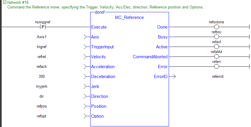
(* MC_Reference ST example *) TriggerInput.InputID := 0; //configure the reference InputID TriggerInput.DIRECTION := 1; //configure the reference direction Inst_MC_Reference( RefReq, Axis1, TriggerInput, 20.0, 100.0, 100.0, 100.0, 0, 0.0, 0 );
|
|
Stay Connected with Kollmorgen       
|
Copyright © 2015 Kollmorgen™ |

|
 [Top]
[Top]