Controlled Stop
In a controlled stop, drive motion is brought to a standstill in a controlled manner. The drive commands a zero velocity from the motor. The motor decelerates at the prescribed deceleration value (AXIS#.CS.DEC ).
A controlled stop can occur in a number of ways:
- The user configures a programmable Action (see Action Table) to perform a Controlled Stop
- Either a controller or the user (through the WorkBench terminal window) initiates a software disable (AXIS#.DIS ) command .
- A fault initiates a controlled stop from the drive. See Faults and Warning Messages for the faults which initiate a controlled stop.
An implicit controlled stop is also part of some other features which stop motion:
- Software & Hardware Limits
- Homing
 The Homing procedure allows, based on a position measurement, to set a position offset to the motor in order to ensure it is physically at the home position processes which have multiple stages of motion
 - AXIS#.DISMODE = 2 and user executes AXIS#.DIS from the terminal or WorkBench disable buttons.
You must disable the drive in order to set AXIS#.DISMODE.
- A fault occurs which has a controlled stop (CS) reaction. After the CS is executed, the drive disables.
- HW limit switch: A digital input is defined as a positive or negative limit switch (AXIS#.HWLS.NEGSOURCE or AXIS#.HWLS.POSSOURCE). When the limit switch is met, the CS mechanism starts running. In this case, the parameter AXIS#.DISTO is not active.
- SW limit switch: SWLS defines an active SW limit. When the limit is met, the CS mechanism starts running. In this case, the parameter AXIS#.DISTO is not active.
Use the drive CS parameters to configure a controlled stop as follows:
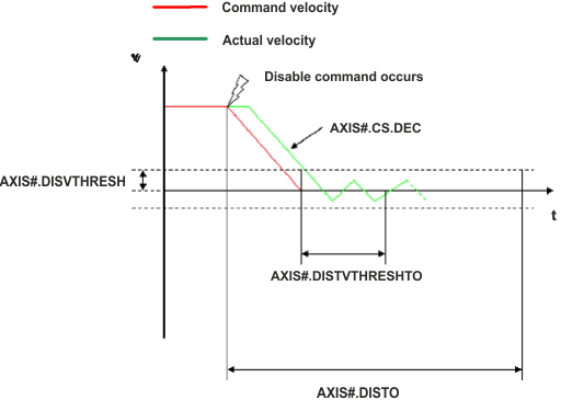
- AXIS#.CS.DEC : Deceleration ramp that is used for disable.
- AXIS#.DISVTHRESH: Velocity 0 threshold. The motor shaft is considered as stopped as soon as the actual velocity (filtered through a 10 Hz filter, such as AXIS#.VL.FBFILTER ) is within ± AXIS#.DISVTHRESH.
- AXIS#.DISTVTHRESH: Velocity 0 time. The actual velocity must be consecutively within 0 ± AXIS#.DISVTHRESH for the time AXIS#.DISTVTHRESHTO, before the drive completes the CS process. This value is used since the motor can overshoot out of the VEL0 window depending on the gains, deceleration ramp, motor inertia and so on.
- AXIS#.DISTO : Disable time out. This parameter sets an overall and independent running check as to whether or not the drive can achieve the disable state. If the VEL0 window set in step 3 is too small, it is possible that the drive may never reach the end of the CS process. The AXIS#.DISTO parameter and functionality addresses this issue by disabling the drive after the AXIS#.DISTO time elapses, even if the CS process did not end.
Controlled Stop Diagram
When configuring the controlled stop feature, please note the following:
- If the HW limit switch is active and any of the other CS activated, the only difference will be that in this case the AXIS#.DISTO will limit the time before disabling the drive.
-
If the value of AXIS#.OPMODE is torque
Torque is the tendency of a force to rotate an object about an axis. Just as a force is a push or a pull, a torque can be thought of as a twist mode, the drive will activate dynamic brake instead of executing a controlled stop. This will help drive the axis to zero velocity even if an external force is being applied to the motor. - Set AXIS#.DISTO to an appropriate value that will allow the motor to decelerate from any velocity to 0 with AXIS#.CS.DEC. This value must also allow the motor to afterward remain within AXIS#.VL.FB for AXIS#.DISTVTHRESH consecutively within 0 ± AXIS#.DISVTHRESH.
The drive issues a fault F6005 in case that the AXIS#.DISTO counter expires during a controlled stop procedure.
Related Topics
|
Stay Connected with Kollmorgen       
|
Copyright © 2018 Kollmorgen |

|