Digital Inputs
The drive provides 8 digital inputs on X21. Dual axis drives and drives with built-in option IO or DX offer additional 4 inputs on X22 and 2 programmable Input/Outputs on X22. If X23 is built-in and not used for feedback or EEO function, then it offers 4 additional programmable Input/Outputs.
All inputs can be used to initiate pre-programmed actions. A list of actions is included in the WorkBench. If an input is programmed, it must be saved to the drive.
The drive provides 4 safe digital inputs on X21 and X22. These inputs can be used as safe inputs, based on the installed functional safety option (see Functional Safety see "Functional Safety").

|
Depending on the selected function, the inputs are high or low active. Digital input filter can be set in WorkBench to change sensitivity of the inputs |
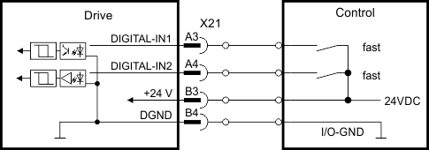
Digital-In 1 and 2
These inputs (IEC![]() "International Electrotechnical Commission"
IEC is a not-for-profit, non-governmental international standards organization that prepares and publishes International Standards for all electrical, electronic and related technologies 61131-2 Type 1) are particularly fast and are therefore suitable for position latch functions. They can also be used as 24 V inputs for electronic gearing .
"International Electrotechnical Commission"
IEC is a not-for-profit, non-governmental international standards organization that prepares and publishes International Standards for all electrical, electronic and related technologies 61131-2 Type 1) are particularly fast and are therefore suitable for position latch functions. They can also be used as 24 V inputs for electronic gearing .
Technical characteristics
- Floating, reference common line is DGND
- High: 11 to 30 V/2 to 15 mA , Low: -5 to +5 V/<15 mA
- Update rate: firmware reads hardware input state every 250 µs
- High accuracy latch: motor feedback position or interpolated time is latched or captured within 2 µs of input signal transition (with digital input filter set to 40 ns)
- The AKD2G capture engine is polled every 62.5 µs (16 kHz) by the firmware
Wiring example
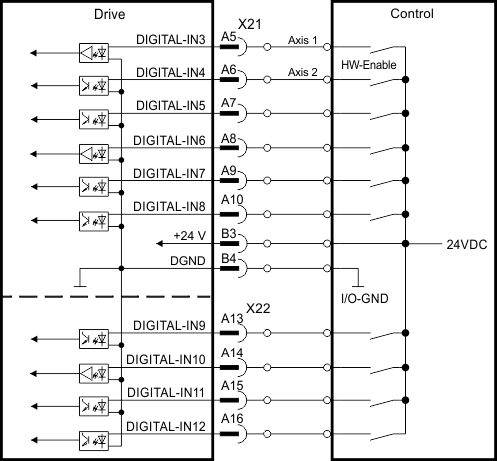
Digital-In 3 to 12
These inputs (IEC 61131-2 Type 1) are programmable with the setup software.
Manufacturer setting:
- Digital-In 3: HW-Enable Axis 1
- Digital-In 4: HW-Enable Axis 2
- Digital-In 5 ...12: off
Choose the function you require in WorkBench. For more information refer to WorkBench.
Technical characteristics
- Floating, reference common line is DGND
- High: 11 to 30 V/2 to 15 mA , Low: -5 to +5 V/<15 mA
- Update rate: firmware reads hardware input state every 250 µs
Wiring example
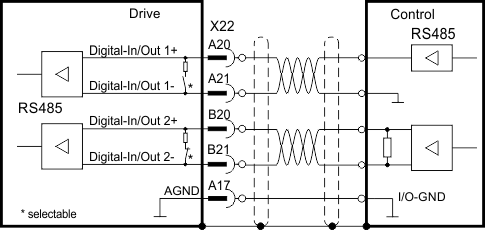
Digital-In/Out 1 and 2
Pins X22/A20-A21 (Digital-In/Out 1) and X22/B20-B21 (Digital-In/Out 2) can be defined as either inputs or outputs. For programming refer to WorkBench.

|
NOT compatible with 24V signal level! Will be damaged if connected to +24V! |
Technical characteristics if configured as input
- RS485, reference common line is AGND
- No wire break detection
- Digital IN/OUT 1/2: Selectable DC termination for differential or single ended input
- Update rate: firmware reads hardware input state every 250 µs
Wiring example
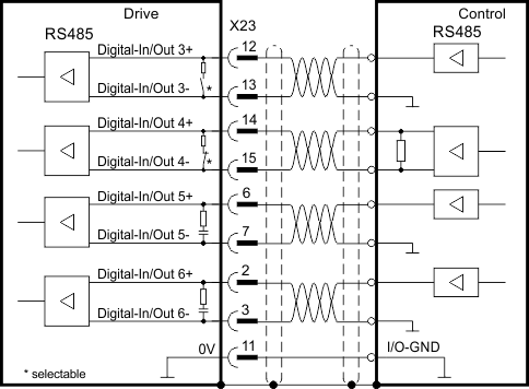
Digital-In/Out 3 to 6
X23 can be used for digital I/O. The channels can be defined as inputs or outputs. For programming refer to WorkBench.
|
|
NOT compatible with 24V signal level! Will be damaged if connected to +24V! |
Technical characteristics if configured as input
- RS485, reference common line is 0V
- No wire break detection
- Digital IN/OUT 3/4: Selectable DC termination for differential or single ended input
- Digital IN/OUT 5/6: AC termination for single ended input
- Update rate: firmware reads hardware input state every 250 µs
Wiring example
|
Stay Connected with Kollmorgen       
|
Copyright © 2018 Kollmorgen |

|