 Power
Power
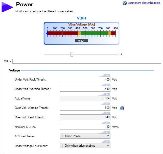
From the Power screen, you can view and configure the drive power settings as follows.
| Element | Description | Parameter |
|---|---|---|
| VBus | Reads the current DC bus voltage on a scale with ranges for faults and warnings. | VBUS.VALUE |
| Under Voltage Fault Threshold | Sets the value at which an under voltage fault will occur | VBUS.UVFTHRESH |
| Under Voltage Warning Threshold | Sets the value at which an under voltage warning will occur | VBUS.UVWTHRESH |
| Actual Value | Displays the current actual voltage value | VBUS.VALUE |
| Over Voltage Warning Threshold | Sets value at which an over voltage warning will occur. Setting a value of 0 generates no warning. | VBUS.OVWTHRESH |
| Over Voltage Fault Threshold | Sets value at which an over voltage fault will occur | VBUS.OVFTHRESH |
| Under Voltage Fault Mode | Sets the behavior for when an under voltage fault are monitored. | VBUS.UVMODE |
| Nominal AC Value | The default operating voltage | VBUS.ACNOMINAL |
See Regeneration for more information about regen resistors and sizing regen resistors.
Operating Voltage
Operating voltage can be selected by the user to allow 480VAC drives to work on 240VAC input supplies.
The VBUS.HALFVOLT parameter has an effect on the following voltage-thresholds:
- DC-bus over-voltage threshold (see VBUS.OVFTHRESH ).
- The regen-resistor enable/disable voltage thresholds.
- The inrush-relay enable/disable voltage thresholds.
A power-cycle is needed after changing the value and saving the parameter on the NV memory of the Drive, since the voltage thresholds mentioned above are read during the boot-sequence of the Drive.
Direct DC Mains Operation
Direct DC input is available on all standard AKD models. The DC input should be run into the AC input connection. Positive and negative DC lines should use L1 and L2 connections (polarity is not critical). L1 and L2 connections are found on either the X3 connector or the X4 connector depending on the model.
The nominal level of DC voltage applied must be compatible with the voltage fault levels in the drive. You must also consider voltage variations in the DC power supply above and below the nominal value so that nuisance faults are avoided.
When you determine the maximum nominal DC voltage applied to the drive, you should also consider the regeneration circuit, in addition to the over voltage level. Running the drive slightly below the over voltage level is not possible because the drive does not have the capability to dissipate regenerated energy. This practice can also be harmful to the regen circuit. A good practice is not to exceed the nominal DC voltage produced by a standard AC installation.
For the AKDzzzz06, 340 VDC is the equivalent DC voltage for a 240 VAC supply and for the AKDxxxx07, 680 VDC is the equivalent DC voltage for a 480 VAC supply.
The voltage fault levels are also shown in the Power screen and depend on the voltage level of drive used.
Voltage ranges are as follows:
|
Model |
Under Voltage Level |
Over Voltage Level |
|---|---|---|
|
AKDzzz06 |
90 VDC |
420 VDC |
|
AKDzzz07 |
380 VDC |
840 VDC |
|
Stay Connected with Kollmorgen       
|
Copyright © 2018 Kollmorgen |

|