AKT2G-SM-Lxx Diagnostic Messages
DiagMessages designates a system for the transmission of messages from the EtherCAT![]() ***EtherCAT is an open, high-performance Ethernet-based fieldbus system. The development goal of EtherCAT was to apply Ethernet to automation applications which require short data update times (also called cycle times) with low communication jitter (for synchronization purposes) and low hardware costs Slave to the EtherCAT Master. The messages are stored by the device in its own CoE under 0x10F3 and can be read by the application. An error message referenced via a code is output for each event stored in the device (warning, error, status change). Diagnostic messages can be viewed from the Diagnostics Tab in the AKT2G-SM-Lxx Stepper Drive Configuration Tab.
***EtherCAT is an open, high-performance Ethernet-based fieldbus system. The development goal of EtherCAT was to apply Ethernet to automation applications which require short data update times (also called cycle times) with low communication jitter (for synchronization purposes) and low hardware costs Slave to the EtherCAT Master. The messages are stored by the device in its own CoE under 0x10F3 and can be read by the application. An error message referenced via a code is output for each event stored in the device (warning, error, status change). Diagnostic messages can be viewed from the Diagnostics Tab in the AKT2G-SM-Lxx Stepper Drive Configuration Tab.
Definition
The DiagMessages system is defined in the ETG (EtherCAT Technology Group) in the guideline ETG.1020, chapter 13 “Diagnosis handling”. It is used so that pre-defined or flexible diagnostic messages can be conveyed from the EtherCAT Slave to the Master. In accordance with the ETG, the process can therefore be implemented supplier-independently. Support is optional. The firmware can store up to 250 DiagMessages in its own CoE.
Each DiagMessage consists of
- Diag Code (4-byte)
- Flags (2-byte; info, warning or error)
- Text ID (2-byte; reference to explanatory text from the ESI/XML
 "Extensible Markup Language "
XML is a general-purpose markup language. It is classified as an extensible language because it allows its users to define their own tags)
"Extensible Markup Language "
XML is a general-purpose markup language. It is classified as an extensible language because it allows its users to define their own tags) - TimestampA timestamp is a sequence of characters, denoting the date and/or time at which a certain event occurred (8-byte, local slave time or 64-bit Distributed Clock time, if available)
- Dynamic parameters added by the firmware
The DiagMessages are explained in text form in the ESI/XML file belonging to the EtherCAT device: on the basis of the Text ID contained in the DiagMessage, the corresponding plain text message can be found in the languages contained in the ESI/XML.
Via the entry NewMessagesAvailable the user receives information that new messages are available.
DiagMessages can be confirmed in the device: the last/latest unconfirmed message can be confirmed by the user.
In the CoE both the control entries and the history itself can be found in the CoE object 0x10F3:
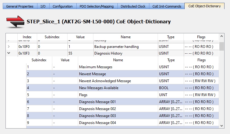
Figure 7-298: Stepper slice objects in the KAS IDE
The subindex of the latest DiagMessage can be read under x10F3:02.
-
-
Support for commissioning
The DiagMessages system is to be used above all during the commissioning of the plant. The diagnostic values e.g. in the StatusWord of the device (if available) are helpful for online diagnosis during the subsequent continuous operation.
Structure of the Text ID
The structure of Kollmorgen EtherCAT devices' MessageID reads as xyzz:
| x | y | zz |
|---|---|---|
|
0: Systeminfo 2: reserved 1: Info 4: Warning 8: Error |
0: System 1: General 2: Communication 3: Encoder 4: Drive 5: Inputs 6: I/O general 7: reserved |
Error number |
For example: Message 0x4413 --> Drive Warning Number 0x13
Overview of Text IDs
Specific text IDs are listed in the device documentation.
|
Text ID |
Type |
Place |
Text Message |
Additional comment |
|---|---|---|---|---|
|
0x0001 |
Information |
System |
No error |
No error |
|
0x0002 |
Information |
System |
Communication established |
Connection established |
|
0x0003 |
Information |
System |
Initialization: 0x%X, 0x %X, 0x%X |
General information; parameters depend on event. See device documentation for interpretation. |
|
0x1000 |
Information |
System |
Information: 0x%X, 0x %X, 0x%X |
General information; parameters depend on event. See device documentation for interpretation. |
|
0x1012 |
Information |
System |
EtherCAT state change Init - PreOp |
|
|
0x1021 |
Information |
System |
EtherCAT state change PreOp - Init |
|
|
0x1024 |
Information |
System |
EtherCAT state change PreOp - Safe-Op |
|
|
0x1042 |
Information |
System |
EtherCAT state change SafeOp - PreOp |
|
|
0x1048 |
Information |
System |
EtherCAT state change SafeOp - Op |
|
|
0x1084 |
Information |
System |
EtherCAT state change Op - SafeOp |
|
|
0x1100 |
Information |
General |
Detection of operation mode completed: 0x%X,%d |
Detection of the mode of operation ended |
|
0x1135 |
Information |
General |
Cycle time o.k.: %d |
Cycle time OK |
|
0x1157 |
Information |
General |
Data manually saved (Idx: 0x%X, SubIdx: 0x%X) |
Data saved manually |
|
0x1158 |
Information |
General |
Data automatically saved (Idx: 0x%X, SubIdx: 0x%X) |
Data saved automatically |
|
0x1159 |
Information |
General |
Data deleted (Idx: 0x%X, SubIdx: 0x%X) |
Data deleted |
|
0x117F |
Information |
General |
Information: 0x%X, 0x %X, 0x%X |
Information |
|
0x1201 |
Information |
Communication |
Communication re-established |
Communication to the field side restored This message appears, for example, if the voltage was removed from the power contacts and re-applied during operation |
|
0x1300 |
Information |
Encoder |
Position set: %d, %d |
Position set - StartInputhandler |
|
0x1303 |
Information |
Encoder |
Encoder Supply ok |
Encoder power supply unit OK |
|
0x1304 |
Information |
Encoder |
Encoder initialization successfully, channel: %X |
Encoder initialization successfully completed |
|
0x1305 |
Information |
Encoder |
Sent command encoder reset, channel: %X |
Send encoder reset command |
|
0x1400 |
Information |
Drive |
Drive is calibrated: %d, %d |
Drive is calibrated |
|
0x1401 |
Information |
Drive |
Actual drive state: 0x%X, %d |
Current drive status |
|
0x1705 |
Information |
|
CPU usage returns in normal range (< 85%%) |
Processor load is back in the normal range |
|
0x1706 |
Information |
|
Channel is not in saturation anymore |
Channel is no longer in saturation |
|
0x1707 |
Information |
|
Channel is not in overload anymore |
Channel is no longer overloaded |
|
0x170A |
Information |
|
No channel range error anymore |
A measuring range error is no longer active |
|
0x170C |
Information |
|
Calibration data saved |
Calibration data were saved |
|
0x170D |
Information |
|
Calibration data will be applied and saved after sending the command “0x5AFE” |
Calibration data are not applied and saved until the command "0x5AFE" is sent |
|
0x4000 |
Warning |
|
Warning: 0x%X, 0x%X, 0x%X |
General warning; parameters depend on event. See device documentation for interpretation. |
|
0x4001 |
Warning |
System |
Warning: 0x%X, 0x%X, 0x%X |
|
|
0x4002 |
Warning |
System |
%s: %s Connection Open (IN:%d OUT:%d API:%dms) from %d.%d.%d.%d successful |
|
|
0x4003 |
Warning |
System |
%s: %s Connection Close (IN:%d OUT:%d) from %d.%d.%d.%d successful |
|
|
0x4004 |
Warning |
System |
%s: %s Connection (IN: %d OUT:%d) with %d.%d.%d.%d timed out |
|
|
0x4005 |
Warning |
System |
%s: %s Connection Open (IN:%d OUT:%d) from %d.%d.%d.%d denied (Error: %u) |
|
|
0x4006 |
Warning |
System |
%s: %s Connection Open (IN:%d OUT:%d) from %d.%d.%d.%d denied (Input Data Size expected: %d Byte(s) received: %d Byte(s)) |
|
|
0x4007 |
Warning |
System |
%s: %s Connection Open (IN:%d OUT:%d) from %d.%d.%d.%d denied (Output Data Size expected: %d Byte(s) received: %d Byte(s)) |
|
|
0x4008 |
Warning |
System |
%s: %s Connection Open (IN:%d OUT:%d) from %d.%d.%d.%d denied (RPI:%dms not supported -> API:%dms) |
|
|
0x4101 |
Warning |
General |
Terminal-Overtemperature |
Overtemperature. The internal temperature of the terminal exceeds the parameterized warning threshold |
|
0x4102 |
Warning |
General |
Discrepancy in the PDOConfiguration |
The selected PDOs do not match the set operating mode. Sample: Drive operates in
velocity mode, but the velocity PDO |
|
0x417F |
Warning |
General |
Warning: 0x%X, 0x%X, 0x%X |
|
|
0x428D |
Warning |
General |
Challenge is not Random |
|
|
0x4300 |
Warning |
Encoder |
Subincrements deactivated: %d, %d |
Sub-increments deactivated (despite activated configuration) |
|
0x4301 |
Warning |
Encoder |
Encoder-Warning |
General encoder error |
|
0x4400 |
Warning |
Drive |
Drive is not calibrated:%d, %d |
Drive is not calibrated |
|
0x4401 |
Warning |
Drive |
Starttype not supported: 0x%X, %d |
Start type is not supported |
|
0x4402 |
Warning |
Drive |
Command rejected: %d,%d |
Command rejected |
|
0x4405 |
Warning |
Drive |
Invalid modulo subtype: %d, %d |
Modulo sub-type invalid |
|
0x4410 |
Warning |
Drive |
Target overrun: %d, %d |
Target position exceeded |
|
0x4411 |
Warning |
Drive |
DC-Link undervoltage (Warning) |
The DC link voltage of the terminal is lower than the parameterized minimum voltage. Activation of the output stage is prevented |
|
0x4412 |
Warning |
Drive |
DC-Link overvoltage (Warning) |
The DC link voltage of the terminal is higher than the parameterized maximum voltage. Activation of the output stage is prevented |
|
0x4413 |
Warning |
Drive |
I2T-Model Amplifier overload (Warning) |
|
|
0x4414 |
Warning |
Drive |
I2T-Model Motor overload (Warning) |
|
|
0x4415 |
Warning |
Drive |
Speed limitation active |
The maximum speed is limited by the parameterized objects (e.g. velocity limitation, motor speed limitation). This warning is output if the set velocity is higher than one of the parameterized limits |
|
0x4416 |
Warning |
Drive |
Step lost detected at position: 0x%X%X |
Step loss detected |
|
0x4417 |
Warning |
Drive |
Motor overtemperature |
The internal temperature of the motor exceeds the parameterized warning threshold |
|
0x4418 |
Warning |
Drive |
Limit: Current |
Limit: current is limited |
|
0x4419 |
Warning |
Drive |
Limit: Amplifier I2T-model exceeds 100%% |
The threshold values for the maximum current were exceeded. |
|
0x441A |
Warning |
Drive |
Limit: Motor I2T-model exceeds 100%% |
Limit: Motor I2T-model exceeds 100% |
|
0x441B |
Warning |
Drive |
Limit: Velocity limitation |
The threshold values for the maximum speed were exceeded. |
|
0x441C |
Warning |
Drive |
STO while the axis was enabled |
An attempt was made to activate the axis, despite the fact that no voltage is present at the STO input. |
|
0x4600 |
Warning |
General IO |
Wrong supply voltage range |
Supply voltage not in the correct range |
|
0x4610 |
Warning |
General IO |
Wrong output voltage range |
Output voltage not in the correct range |
|
0x4705 |
Warning |
|
Processor usage at %d %% |
Processor load at %d %% |
|
0x470A |
Warning |
|
EtherCAT Frame |
EtherCAT frame missed (change DC Operation Mode or Sync0 Shift Time under Settings) |
|
0x8000 |
Error |
System |
%s: %s |
|
|
0x8001 |
Error |
System |
Error: 0x%X, 0x%X, 0x %X |
General error; parameters depend on event. See device documentation for interpretation. |
|
0x8002 |
Error |
System |
Communication aborted |
Communication aborted |
|
0x8003 |
Error |
System |
Configuration error: 0x %X, 0x%X, 0x%X |
General; parameters depend on event. See device documentation for interpretation. |
|
0x8004 |
Error |
System |
%s: Unsuccessful FwdOpen-Response received from %d.%d.%d. %d (%s) (Error: %u) |
|
|
0x8005 |
Error |
System |
%s: FwdClose-Request sent to %d.%d.%d.%d (%s) |
|
|
0x8006 |
Error |
System |
%s: Unsuccessful FwdClose-Response received from %d.%d.%d. %d (%s) (Error: %u) |
|
|
0x8007 |
Error |
System |
%s: Connection with %d. %d.%d.%d (%s) closed |
|
|
0x8100 |
Error |
General |
Status word set: 0x%X, %d |
Error bit set in the status word |
|
0x8101 |
Error |
General |
Operation mode incompatible to PDO interface: 0x%X, %d |
Mode of operation incompatible with the PDO interface |
|
0x8102 |
Error |
General |
Invalid combination of Inputs and Outputs PDOs |
Invalid combination of input and output PDOs |
|
0x8103 |
Error |
General |
No variable linkage |
No variables linked |
|
0x8104 |
Error |
General |
Terminal-Overtemperature |
The internal temperature of the terminal exceeds the parameterized error threshold. Activation of the terminal is prevented |
|
0x8105 |
Error |
General |
Communication between the fieldbus and the output stage is secured by a Watchdog. The axis is stopped automatically if the fieldbus communication is interrupted.
|
|
|
0x8135 |
Error |
General |
Cycle time has to be a multiple of 125 µs |
The IO or NC cycle time divided by 125 µs does not produce a whole number |
|
0x8136 |
Error |
General |
Configuration error: invalid sampling rate |
Configuration error: Invalid sampling rate |
|
0x8137 |
Error |
General |
Content of the external name plate memory invalid. |
|
|
0x8140 |
Error |
General |
Sync Error |
Real-time violation |
|
0x8141 |
Error |
General |
Sync%X Interrupt lost |
|
|
0x8142 |
Error |
General |
Sync Interrupt asynchronous |
Sync Interrupt asynchronous |
|
0x8143 |
Error |
General |
Jitter too big |
Jitter limit violation |
|
0x817F |
Error |
General |
Error: 0x%X, 0x%X, 0x%X |
|
|
0x8200 |
Error |
Communication |
Write access error: %d, %d |
Error while writing |
|
0x8201 |
Error |
Communication |
No communication to field-side (Auxiliary voltage missing) |
|
|
0x8281 |
Error |
Communication |
Ownership failed: %X |
|
|
0x8282 |
Error |
Communication |
To many Keys founded |
|
|
0x8283 |
Error |
Communication |
Key Creation failed: %X |
|
|
0x8284 |
Error |
Communication |
Key loading failed |
|
|
0x8285 |
Error |
Communication |
Reading Public Key failed: %X |
|
|
0x8286 |
Error |
Communication |
Reading Public EK failed: %X |
|
|
0x8287 |
Error |
Communication |
Reading PCR Value failed: %X |
|


