AKT2G-SM-Lxx Stepper Drive Configuration Tab
This tab is used to configure the device, based on the parameters of the stepper motor being used, and to diagnose any problems with the stepper terminal. To make configuration simple, a Kollmorgen stepper motor can be selected from the Properties Tab, which will automatically populate the stepper motor parameter fields. The stepper motor parameters can also be easily replicated to a file, and transferred between devices. Once the project is compiled the CoE Init Commands tab will be populated based on these values. Troubleshooting the stepper terminal can begin by gathering information from the Diagnostics Tab
Properties Tab
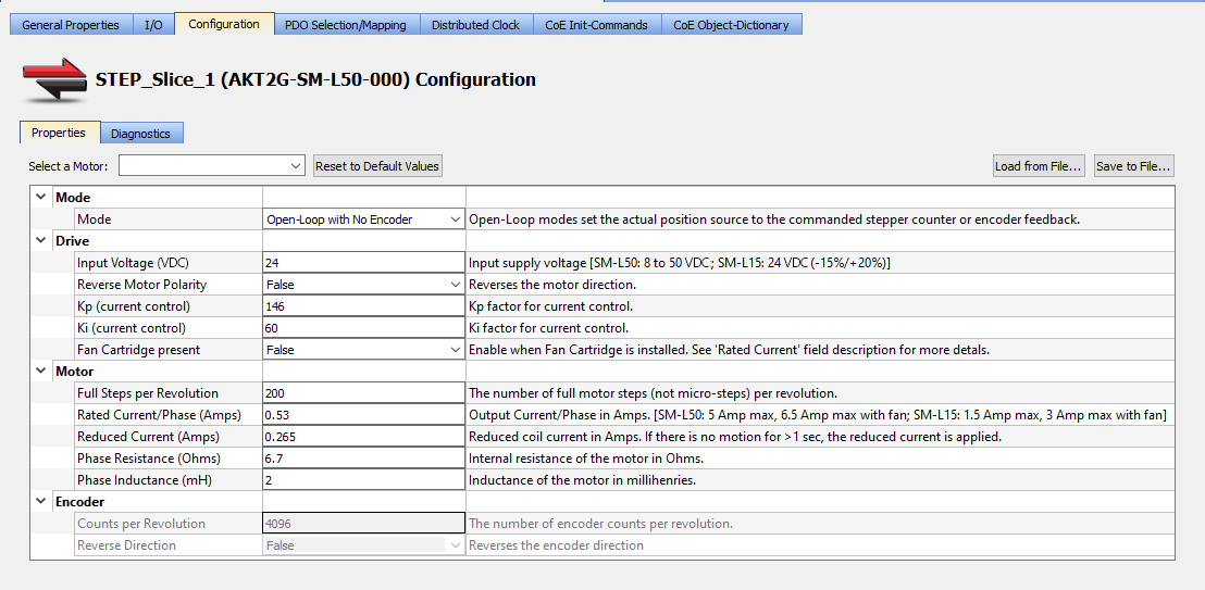
- Select a Motor
- The drop-down list contains nearly 500 Kollmorgen stepper motor models and their specific parameters. Selecting a model automatically populates the appropriate motor-specific fields. See the Kollmorgen Stepper Optimizer if you need to match a motor series name to the model number.
- Reset to Default Values
- Clicking this button will change all of the stepper motor parameters to the default values.
- Load from File…
- This function prompts you to select an XML
 "Extensible Markup Language "
XML is a general-purpose markup language. It is classified as an extensible language because it allows its users to define their own tags file to populate all of the stepper parameters, not just those specific to the motor.
"Extensible Markup Language "
XML is a general-purpose markup language. It is classified as an extensible language because it allows its users to define their own tags file to populate all of the stepper parameters, not just those specific to the motor. - Save to File…
- This function creates an XML file containing all of the current stepper parameters, which is easily stored or transferred between devices.
| Section | Element | Description |
|---|---|---|
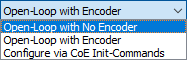
| Mode | Mode | Select the CoE object used for the actual position.
|
| Drive | Input Voltage (VDC) | Specify the input supply voltage. Range is:
|
| Reverse Motor Polarity | Select True or False from the drop-down menu to reverse the motor direction. | |
| Speed Range | Select the maximum output full-step frequency from the drop-down list. | |
| Kp (current control) | Specify the proportional gain factor for current control. | |
| Ki (current control) | Specify the integral gain factor for current control. | |
| Fan Cartridge Present | Set this to "True" if a AKT2G-AC-FAN-001 fan cartridge is installed. Having a fan present allows you to set the Rated Current / Phase (Amps) to a higher value. | |
| Motor | Full Steps per Revolution | Specify the number of full motor steps per revolution. |
| Rated Current / Phase (Amps) |
Specify the motor’s rated current per phase in Amps. This is also known as the RMS (root mean square) current. This value will be converted from RMS to Peak output current, by multiplying the value by 1.414 (square root of 2) to specify the maximum output current for the stepper drive. The 64x microstep resolution causes a 30 percent current loss compared to full-step resolution. This is due to the output wave form being closer to a sine wave than a square wave. The rated current/phase value is converted to the peak output current to compensate for the current loss. Since the peak output current may exceed the motor’s rated current per phase at standstill, it is very important to configure the Reduced Current/Phase (Amps), to prevent the motor from overheating. Maximum Motor Current/Phase (RMS) values are:
Maximum converted Peak output values are:
|
|
| Reduced Current/Phase (Amps) |
Specify the motor’s current per phase in Amps when at standstill. This is also known as the RMS (root mean square) current. This value will be converted from RMS to Peak output current, by multiplying the value by 1.414 (square root of 2) to specify the maximum output current for the stepper drive when the motor is at standstill. The Reduced Peak Current is applied when there is no motion for > 1 sec. At a minimum, the Reduced Current/Phase can be set to 70% of the Rated Current / Phase (Amps). Setting the Reduced Current/Phase to 50% (or lower) of the Rated Current/Phase is recommended. |
|
| Phase Resistance (Ohms) | Specify the internal resistance of the motor in Ohms. | |
| Phase Inductance (mH) | Specify the motor's inductance in millihenries. | |
| Encoder | Counts per Revolution | Specify the number of encoder counts per revolution. |
| Reverse Direction | Select True or False from the drop-down menu to reverse the encoder direction. |
-
-
- See Add and Configure I/O Slices for adding a stepper drive to your project.
- For information on the devices see AKT2G-SM-L15-000 or AKT2G-SM-L50-000.
- See AKT2G-SM-Lx Object Description for stepper drive-specific object descriptions.
Diagnostics Tab
This tab gathers the diagnostic messages available on the connected stepper terminal. This information may be used for troubleshooting during commissioning or operation. The PLC![]() "Programmable Logic Controller"
A Programmable Logic Controller, PLC, or Programmable Controller is a digital computer used for automation of industrial processes, such as control of machinery on factory assembly lines.
Used to synchronize the flow of inputs from (physical) sensors and events with the flow of outputs to actuators and events application must be running on a controller or Online Configuration mode must be enabled to acquire diagnostics data.
"Programmable Logic Controller"
A Programmable Logic Controller, PLC, or Programmable Controller is a digital computer used for automation of industrial processes, such as control of machinery on factory assembly lines.
Used to synchronize the flow of inputs from (physical) sensors and events with the flow of outputs to actuators and events application must be running on a controller or Online Configuration mode must be enabled to acquire diagnostics data.
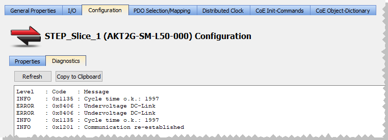
- Refresh
- Clicking this button reads and displays the stepper terminal's messages. A comprehensive list of messages may be found in AKT2G-SM-Lxx Diagnostic Messages. This button is disabled under the following conditions.
-
- The PLC application is neither running nor in online configuration mode.
- A stepper I/O slice is not present on the EtherCAT***EtherCAT is an open, high-performance Ethernet-based fieldbus system. The development goal of EtherCAT was to apply Ethernet to automation applications which require short data update times (also called cycle times) with low communication jitter (for synchronization purposes) and low hardware costs network e.g. offline device
- The PLC application is running on the KAS Simulator.
- Copy To Clipboard
- Clicking this button copies the message data.
- Connect to your controller.

- Compile and download the application.

- Enable Online Configuration Mode.

- OR -
Start the application.


