EtherCAT Diagnostic LEDs
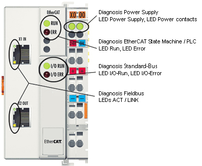
After switching on, the ETHERCAT Bus Coupler immediately checks the connected configuration. Error-free start-up is indicated when the red I/O ERR LED goes out. If the I/O ERR LED blinks, an error in the area of the terminals is indicated. The error code can be determined from the frequency and number of blinks. See below for more information.
The ETHERCAT Bus Coupler has respectively a green and yellow LED at the RJ45 plug sockets, which indicate the state of the fieldbus (Figure 4.1). The RUN and ERROR LEDs (upper middle) indicate the state of the EtherCAT![]() ***EtherCAT is an open, high-performance Ethernet-based fieldbus system. The development goal of EtherCAT was to apply Ethernet to automation applications which require short data update times (also called cycle times) with low communication jitter (for synchronization purposes) and low hardware costs State Machine.
***EtherCAT is an open, high-performance Ethernet-based fieldbus system. The development goal of EtherCAT was to apply Ethernet to automation applications which require short data update times (also called cycle times) with low communication jitter (for synchronization purposes) and low hardware costs State Machine.
On the upper right hand side of the Bus Couplers are two more green LEDs that indicate the supply voltage. The left hand LED indicates the presence of the 24 V supply for the Bus Coupler. The right hand LED indicates the presence of the supply to the power contacts.


