Commissioning AKT2G-ENC-180-000
Basic function principles
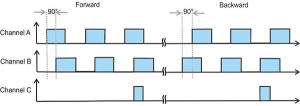
The terminal acquires the 90° phase-shifted digital output signal of an incremental encoder on channels A and B. The zero pulse is acquired on channel C. These signals are converted into a position value with quadruple evaluation with the aid of the quadrature encoder and the 32-bit counter. The latch and reset functions enable the exact referencing and saving of the counter value, irrespective of the speed.
Incremental encoders divide a 360° rotation of the encoder axis into individual steps (increments) and mark a full revolution by means of a special mark (zero pulse).
The phase angle between the signals on channels A and B sets the counting direction.
Up: signal on channel A leads signal on channel B by 90°
Down: signal on channel A lags signal on channel B by 90°
In case of single evaluation, the positive edges on channel A are counted.
In case of quadruple evaluation, the positive and negative edges on channel A and channel B are counted.
Figure 8-24: Quadrature decoder
Whereas absolute value encoders deliver an absolute and unambiguous position value over the complete travel path directly after switching on, it is necessary with incremental encoders to perform a reference run homing after switching on in order to be able to determine an unambiguous position.
Referencing can be carried out, for example, with the aid of reference cams or using the zero pulse of the encoder.
Operating modes and settings
General
The AKT2G-ENC-180 incremental encoder interface terminal enables connection of incremental encoders with the Bus Coupler or the PLC![]() "Programmable Logic Controller"
A Programmable Logic Controller, PLC, or Programmable Controller is a digital computer used for automation of industrial processes, such as control of machinery on factory assembly lines.
Used to synchronize the flow of inputs from (physical) sensors and events with the flow of outputs to actuators and events. A 32-bit counter with quadrature decoder as well as a 32-bit latch can be read, set or activated (switchable to 16-bit). In addition to the encoder inputs A, B and C, a gate/latch input (24 V) is also available on the AKT2G-ENC-180 for latching/saving the counter value. The gate/latch input is parameterizable via the CoE directory. no function, or disabling the counter at HIGH or LOW signal level.
"Programmable Logic Controller"
A Programmable Logic Controller, PLC, or Programmable Controller is a digital computer used for automation of industrial processes, such as control of machinery on factory assembly lines.
Used to synchronize the flow of inputs from (physical) sensors and events with the flow of outputs to actuators and events. A 32-bit counter with quadrature decoder as well as a 32-bit latch can be read, set or activated (switchable to 16-bit). In addition to the encoder inputs A, B and C, a gate/latch input (24 V) is also available on the AKT2G-ENC-180 for latching/saving the counter value. The gate/latch input is parameterizable via the CoE directory. no function, or disabling the counter at HIGH or LOW signal level.
The AKT2G-ENC-180 can also be used as a single-channel 32/16 bit counter on channel A, in which case the signal level on channel B defines the count direction. The changeover to this mode takes place via the CoE directory.
The Counter Value input value represents a 32-bit “position counter”. At the period input the period between two positive edges of channel A is measured with a resolution of 100 ns (default setting, decimal value x 100 ns). Depending on the setting (index 0x8000:14, index 0x8000:16), the period length may be up to 1.6 s or 3.2 s.
Operating modes
Permissible operating modes for the AKT2G-ENC-180
The following modes are available for the AKT2G-ENC-180. They apply both for the encoder analysis and counter terminal mode.
The combinations of DC, PDO![]() PDO is a type of protocol frame used in some fieldbuses. A PDO contains one or more object dictionary entries, which define the application data transferred between devices. and CoE settings listed below are permissible per mode. Other settings can lead to irregular process data and error messages in the Safety PLC System Manager Logger window.
PDO is a type of protocol frame used in some fieldbuses. A PDO contains one or more object dictionary entries, which define the application data transferred between devices. and CoE settings listed below are permissible per mode. Other settings can lead to irregular process data and error messages in the Safety PLC System Manager Logger window.
| Mode | DC | Pain PDO | Optional PDO 1 | Optional PDO 2 | Features CoE |
|---|---|---|---|---|---|
| 1 | FreeRun |
Predefined PDO Assignment: Standard 32-bit (MDP 511): 0x1A00 + 0x1600 + 0x1A02 | CoE combinations 0x8000:nn | ||
|
0x1A00 Inputs: + 0x1600 Outputs: |
0x1A02 or 0x1A03 |
-- | |||
| 2 | FreeRun | Predefined PDO Assignment: Standard 16-bit (MDP 511): 0x1A01 + 0x1601 + 0x1A02 | CoE combinations 0x8000:nn | ||
|
0x1A01 Inputs: + 0x1601 Outputs: |
0x1A02 or 0x1A03 |
-- | |||
| 3 | DC/DCi |
Predefined PDO Assignment: |
CoE combinations 0x8000:nn |
||
|
0x1A00 Inputs: + 0x1600 Outputs: |
0x1A02 or 0x1A03 |
0x1A04 or 0x1A05 |
|||
| 4 | DC/DCi |
Predefined PDO Assignment: |
CoE combinations 0x8000:nn | ||
|
0x1A01 Inputs: + 0x1601 Outputs: |
0x1A02 or 0x1A03 |
0x1A04 or 0x1A05 |
|||
Explanatory notes for parameters and modes
Frequency
- The timeframe for the frequency calculation as well as the resolution can be parameterized in the CoE objects Frequency window (index: 0x80n0:11), Frequency scaling (index: 0x80n0:13), Frequency resolution (index: 0x80n0:15) and Frequency wait time (index: 0x80n0:17). • The positive edges of track A are counted in the specified timeframe (see Frequency modes) and the next subsequent edge including the time until it arrives is counted. The waiting time for the edge can be set in the CoE object Frequency Wait Time (index: 0x80n0:17) (unit: ms) and is set as standard to 1.6 seconds. This is also the maximum value.
- The frequency is always specified as a positive number, irrespective of the sense of rotation.
- The size of the timeframe is 10 ms (default), but at the least the basic unit Frequency window base (index: 0x80n0:0F).
- This calculation is carried out in the terminal in free-running mode without reference to the distributed clocks system. It is therefore independent of the DC mode.
- AKT2G-ENC-180: No frequency measurement is possible if the counter is blocked by the gate. In this case the period can be measured regardless.
- AKT2G-ENC-180: A C or external reset restarts the frequency measurement. The last frequency value remains unchanged until a new frequency value is determined.
- The object Frequency window base (index: 0x80n0:0F) is used for switching the basic unit for the Frequency window between 1 µs and 1 ms, in order to adjust the time window for the measurement. The following maximum measuring windows are therefore possible:
Basic unit
Max. timeframe
1 µs
65.5 ms
1 ms
65 s
- on expiry of the measuring window Frequency window (index: 0x80n0:11), the subsequent positive edge on track A is awaited, but at the longest for 1.6 s or the time from Frequency wait time (index: 0x80n0:17).
- The frequency is measured with different accuracies depending on the selected basic unit Frequency window base (index 0x80n0:0F) and the window size.
Frequency mode A
The measurement is automatically performed in frequency mode A if the window size is smaller than or equal to 600 ms.
- Basic unit 1 µs: all window sizes
- Basic unit 1 ms: up to 600 ms window size
Measurement sequence
- The measurement starts with a positive edge at track A. The current counter value and time (resolution: 100 ns) are stored.
- On expiry of the measuring window Frequency window (index: 0x80n0:11), the subsequent rising edge
 A rising edge is the transition of a digital signal from low to high. It is also called positive edge on track A is awaited, but at the longest for 1.6 s or the time from Frequency wait time (index: 0x80n0:17).
 - The frequency is calculated from the edge difference and the actual elapsed time.

Figure 8-25: Frequency measurement principle - frequency mode A
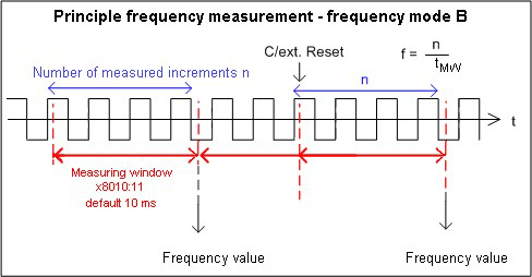
Frequency mode B
The measurement is automatically performed in frequency mode B if the window size is greater than 600 ms.
- Basic unit 1 ms: from 601 ms window size
Measurement sequence
- At the start of the measurement the time and the current position are stored with a resolution of 100 ns, irrespective of the current signal position.
- After the measurement the current position is stored irrespective of the current signal position.
- The frequency is calculated from the number of increments and the actual elapsed time.
- The frequency measurement therefore takes place with reduced accuracy.
- The larger the measuring window in relation to the basic unit, the more precise the frequency calculation.

Figure 8-26: Frequency measurement principle - frequency mode B
Period calculation
- This calculation is carried out free-running in the slave without reference to the distributed clocks system. It is therefore independent of the DC mode.
- During each cycle the interval between two positive edges of input A is counted.
- Depending on the setting, periods of up to 1.6 s or 3.2 s in length are measurable.
- If no edge change occurs for approx. 1.6 s, any period specification is cancelled.
Gate function
The counter can be latched with the aid of the gate function. The Gate polarity object (index: 0x8000:04) provides three different options:
0: The gate function is inactive.
1: The counter value is latched by a HIGH level at the gate input. The counter value does not change as long as the HIGH level is applied. Signals on channels A and B have no effect on the counter value.
2: The counter value is locked by a LOW level at the gate input. The counter value does not change as long as the LOW level is applied. Signals on channels A and B have no effect on the counter value.
In the case of a simultaneous activation of the gate function (latch on HIGH level / latch on LOW level) and Enable extern reset (reset on positive edge / reset on negative edge), the counter value is first reset to zero. Latching subsequently takes place.
Latch
Activating the latch C input (“C”) and latching the counter value
- The counter value is saved in Latch value (index: 0x6000:12) upon the first latch pulse (positive edge on input “C”) after setting the bit (TRUE) in Enable latch C (index: 0x7000:01) (takes priority over Enable latch extern on positive / negative edge index: 0x7000:02 / 0x7000:04). If the bit is set, the subsequent pulses on the other inputs have no effect on the latch value in Latch value (index: 0x6000:12).
- After re-activation of Enable latch C (index: 0x7000:01), the next counter value at the latch input can be written only if the value of the Latch C valid bit (index 0x6000:01 FALSE) has been reset.
Activation of the external latch input and saving (“latching”) of the counter value (index 0x7000:02, 0x7000:04)
- The counter value at the latch input Latch value (index 0x6000:12) will be saved upon the first external latch pulse with a positive edge if the bit (TRUE) is set in Enable extern latch on positive edge (index: 0x7000: 02). The subsequent pulses have no influence on the latch value in Latch value (index: 0x6000:12).
- The counter value at the latch input Latch value (index: 0x6000:12) will be saved upon the first external latch pulse with a negative edge if the bit (TRUE) is set in Enable extern latch on negative edge (index: 0x7000: 04). The subsequent pulses have no influence on the latch value in Latch value (index: 0x6000:12).
- After re-activation, a new counter value on the latch input can be written only if the value of the Latch extern valid bit (index: 0x6000:02) has been reset.
Reset
The counter can be reset via Enable C reset (index: 0x8000:01) or via Enable extern reset (index: 0x8000:02). Extern reset polarity (index: 0x8000:10) defines whether the reset takes place on a positive or negative edge at the external latch input.
“Enable C reset” (index: 0x8000:01)
- For activation the bit in Enable C reset (index: 0x8000:01) is set to TRUE.
The counter value is reset to zero if the zero pulse is present on channel C.
“Enable extern reset” (index: 0x8000:02),
- For activation the bit in Enable extern reset (index: 0x8000:02) is set to TRUE.
- “Extern reset polarity” (index: 0x8000:10)
- Bit not set: the counter is set to zero with a negative edge at the external latch input.
- Bit set: the counter is set to zero with a positive edge at the external latch input.
The simultaneous activation of the functions Enable C reset (index: 0x8000:01) und Enable extern reset (index: 0x8000:02) is not possible.
Up/down counter
- The operating mode (encoder or up/down counter) is selected via the CoE object Enable up/down counter (index: 0x80n0:03).
On the CoE - Online tab, click on the row of the index to be parameterized, enter the corresponding value in the SetValue dialog and confirm with OK.
- 0: the up/down counter is not active.
- 1: the up/down counter is active. • In the case of the AKT2G-ENC-180 the counter value can be locked via the object Gate polarity (index:
0x8000:04) (s. Gate function).
- The counting direction (up/down) is specified via the signal level at channel B. • An additional option for reversing the direction of rotation is to set the Reversion of rotation bit (index: 0x80n0:0E).
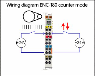
- Connection:

Figure 8-27: Counter connection principle
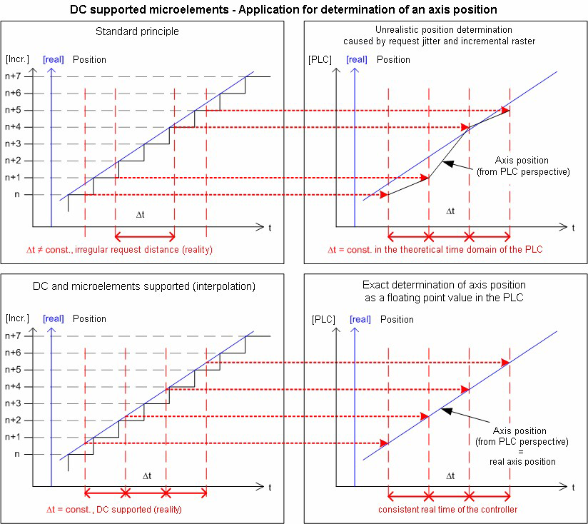
Micro-increments
- Works with and without distributed clocks, but in the AKT2G-ENC-180 this is only meaningful in conjunction with one of the DC modes
- By setting the counter value only the integer component can be modified.
-
The principle:

The highly constant query cycles (accuracy: 100 ns) of the distributed clocks system permits the AKT2G-ENC-180 to interpolate interpolated axis positions between the counted encoder increments above a certain speed. The interpolation resolution is 8 bit, corresponding to 256 values. A standard encoder with 1,024 bars with 4-way evaluation and micro-increments thus becomes a high-resolution axis encoder with 4096 * 256 = 1,048,567 bars.
If the speed falls below the minimum speed, this is displayed by the object Extrapolation stall (index: 0x60n0:08) in the process data.
Digital filter
The AKT2G-ENC-180 has a digital filter on encoder channels A and B that can be switched off (object Disable Filter, index: 0x80n0:08). This acts as a diffuse low-pass filter at about 100 KHz (equals 400,000 increments/second with 4-fold evaluation), i.e. the permissible limit frequency.
In each application it is advisable to check whether it would be advantageous to deactivate the filter - the detection of fast axis movements may be improved as a result.


