![]()
 Function Block
![]() A function block groups an algorithm and a set of private data. It has inputs and outputs. - Facilitates dancer and tension control in an electronic geared master/slave machine design.
A function block groups an algorithm and a set of private data. It has inputs and outputs. - Facilitates dancer and tension control in an electronic geared master/slave machine design.
Inputs
|
Input |
Data Type |
Range |
Unit |
Default |
Description |
|---|---|---|---|---|---|
|
Enable |
BOOL |
0, 1 |
N/A |
No default |
Enables execution. |
|
MasterID |
AXIS_REF |
N/A |
N/A |
No default |
Master axis identifier. |
|
SlaveID |
AXIS_REF |
N/A |
N/A |
No default |
Slave axis identifier. |
|
RatioNumerator |
DINT |
-2147483648 to 2147483647 |
N/A |
No default |
Numerator of master/slave ratio. |
|
RatioDenominator |
DINT |
-2147483648 to 2147483647 |
N/A |
No default |
Denominator of master/slave ratio. |
|
Acceleration |
LREAL |
-1.7E308 to 1.7E308 |
N/A |
No default |
Trapezoidal: Acceleration rate.
|
|
Deceleration |
LREAL |
-1.7E308 to 1.7E308 |
N/A |
No default |
Trapezoidal: Deceleration rate.
|
|
LREAL |
-1.7E308 to 1.7E308 |
N/A |
No default |
Trapezoidal: 0 (zero).
|
|
|
Kp |
LREAL |
-1.7E308 to 1.7E308 |
N/A |
No default |
Proportional gain. 14 to 15 significant digits of accuracy. |
|
Ti |
LREAL |
-1.7E308 to 1.7E308 |
N/A |
No default |
Integral gain. 14 to 15 significant digits of accuracy. |
|
Td |
LREAL |
-1.7E308 to 1.7E308 |
N/A |
No default |
Derivative gain. 14 to 15 significant digits of accuracy. |
|
DeviceFBValue |
DINT |
-2147483648 to 2147483647 |
N/A |
No default |
Analog input. |
|
DeviceSetPoint |
DINT |
-2147483648 to 2147483647 |
N/A |
No default |
Analog set point. |
|
ErrorDB |
LREAL |
-1.7E308 to 1.7E308 |
N/A |
No default |
Maximum or minimum error between DeviceFBValue and DeviceSetPoint before a change takes place. 14 to 15 significant digits of accuracy. |
|
RatioLimitPercent |
LREAL |
-1.7E308 to 1.7E308 |
N/A |
No default |
Maximum and minimum master/slave ratio window. 14 to 15 significant digits of accuracy. |
|
ErrorCalcMode |
BOOL |
0, 1 |
N/A |
No default |
|
Outputs
|
Output |
Data Type |
Range |
Unit |
Description |
|---|---|---|---|---|
|
OK |
BOOL |
0, 1 |
N/A |
The output has power flow after the enable input has been energized. |
|
NewRatio |
REAL |
-3.4E38 to 3.4E38 |
N/A |
New master/slave ratio. 6 to 7 significant digits of accuracy. |
|
Error |
BOOL |
0, 1 |
N/A |
|
|
ErrorID |
INT |
-32768 to +32767 |
N/A |
Function block error value. |
Remarks
- This facilitation is done by using the analog feedback from an LVDT, tension transducer, potentiometer, encoder, resolver or some other similar device.
- The analog feedback value is compared to a pre-determined analog set-point.
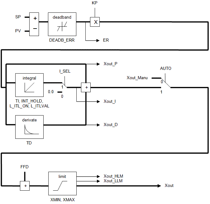
- The difference or error is used in a PID
 "Proportional-Integral-Derivative"
A PID controller is a generic control-loop feedback mechanism widely used in industrial control systems.
An "error" occurs when an event or a disturbance triggers off a change in the process variable.
A PID controller attempts to correct the error between a measured process variable and a desired setpoint by calculating and then outputting a corrective action that can adjust the process accordingly algorithm with the summed output driving changes to the master/slave gearing relationship.
"Proportional-Integral-Derivative"
A PID controller is a generic control-loop feedback mechanism widely used in industrial control systems.
An "error" occurs when an event or a disturbance triggers off a change in the process variable.
A PID controller attempts to correct the error between a measured process variable and a desired setpoint by calculating and then outputting a corrective action that can adjust the process accordingly algorithm with the summed output driving changes to the master/slave gearing relationship. - This results in the slave axis either speeding up or slowing down to maintain desired tension.
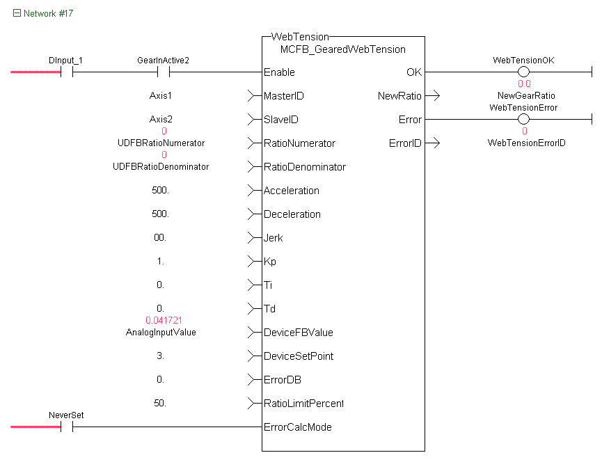
This image shows the function or function block I/O.

Figure 6-104: MCFB_GearedWebTension
Usage
- This UDFB "User Defined Function Block"
UDFB can be used as a sub-function block in another program of the application. It is described using FBD, LD, ST or IL language. Input / output parameters of a UDFB (as well as private variables) are declared in the variable editor as local variables of the UDFB is used in conjunction with the main ladder MC_GearIn function.
- It is assumed that the master/slave move is active.
- Internal to the UDFB is another call to the MC_GearIn function.
- Therefore, the MasterID, SlaveID, RatioNumerator, RatioDenominator, Acceleration, Deceleration, and Jerk inputs are the same values as the main ladder MC_GearIn function input values, both with the Buffer input of 0 (zero).
- This assures that the initial starting master/slave ratio will transition to the new Kollmorgen UDFB ratio smoothly.
- This UDFB changes the master/slave ratio defined by the MC_GearIn function based on the error between the analog input and the analog set-point.
- The magnitude of the ratio and the rate of the ratio change is defined by the Kp, Ti, Td PID gain values.
- The new ratio calculated is output at the NewRatio output.
- The RatioLimitPercent input is the maximum and minimum theoretical new ratio that can be changed.
- This provides a +/- window limit around the running ratio to prevent unwanted motion in the event of a web break or analog feedback failure.
Example 1
-
-
This example assumes the analog feedback device
A process whereby some proportion of the output signal of a system is passed (fed back) to the input.
In automation, a device coupled to each motor to provide indication of the motor's shaft angle, for use in commutating the motor and controlling its speed and position is located after (or downstream in the process) the feedroll axis.
RatioNumerator = 1
RatioDenominator = 2     Therefore the master/slave starting ratio is 0.5000000
ErrorCaclMode = 0
DeviceFBValue = 6
DeviceSetPoint = 4    Therefore error 6 – 4 = 2
Kp = 0.005
Ti = 0
Td= 0
From the equation:
New RatioDenominator = (RatioDenominator - Kp * error)
- The new RatioDenominator = (2 - 0.005*2) = 1.99.
- The new master/slave running ratio is 1 / 1.99 = 0.502512562.
- Since the master/slave ratio is greater than the previous ratio, the slave axis is going faster and the tension is reduced.
Example 2
-
-
This example assumes the analog feedback device is located before (or upstream in the process) the feedroll axis.
RatioNumerator = 1
RatioDenominator = 2     Therefore the master/slave starting ratio is 0.5000000
ErrorCaclMode = 1
DeviceFBValue = 6
DeviceSetPoint = 4    Therefore error is 4 – 6 = -2
Kp = 0.005
Ti = 0
Td= 0
From the equation:
New RatioDenominator = (RatioDenominator – (Kp * error))
- The new RatioDenominator = (2 + 0.005*2) = 2.01.
- The new master/slave running ratio is 1 / 2.01 = 0.497512437.
- Since the master/slave ratio is less than the previous ratio, the slave axis is going slower and the tension is reduced.
PID Function in KAS
There is a PID function in KAS that could be used for the PID control section in the UDFB.
Programming Tips
- The FB_FirstOrderDigitalFilter UDFB can be used to decrease excess dither on the analog input.
- The filtered analog value is then used at the DeviceFBValue input of the MCFB_GearedWebTension UDFB.
- The assumption is an MC_GearIn function block is first called in the main ladder and these initial values are used at the inputs for the UDFB.
- The resolution of the initial MC_GearIn the RatioNumerator and RatioDenominator inputs are directly related to the resolution of the calculated master/slave ratio (from the UDFB inputs) and may need to be scaled accordingly.
Example 1
No scaling
Initial MC_GearIn input RatioNumerator = 2.
Initial MC_GearIn input RatioDenominator = 1 then initial Master/Slave ratio = 2.
UDFB input RatioNumerator = 2.
UDFB input RatioDenominator = 1 then UDFB Master/Slave ratio = 2.
UDFB input DeviceFBValue = 4.
UDFB input DeviceFBSetpoint = 3 then Device PID error = 1 assume KP = 1, Ti and Td =0.
New UDFB RatioNumerator = Current RatioNumerator – PID error = 2 – 1 = 1 then new UDFB Master/Slave ratio = 1.
Resolution = Master/Slave ratio:PID Error ratio = 1:1.
- The resolution is so coarse that a change of 1 for the error output of the PID creates a Master/Slave ratio change of 1.
- This result is a significant change to the slave velocity that will probably cause excess slack or web breakage.
Example 2
Scaling value = 1000
Initial MC_GearIn input RatioNumerator = 2.
Initial MC_GearIn input RatioDenominator = 1 then initial Master/Slave ratio = 2.
UDFB input RatioNumerator = 2000
UDFB input RatioDenominator = 1000 then UDFB Master/Slave ratio = 2.
UDFB input DeviceFBValue = 4.
UDFB input DeviceFBSetpoint = 3 then Device PID error = 1 assume KP = 1, Ti and Td =0.
New UDFB RatioNumerator = Current RatioNumerator – PID error = 2000– 1 =1999 then new UDFB Master/Slave ratio = 1999.
Resolution = Master/Slave ratio: PID Error ratio = 2000:1.
- This resolution is much finer than Example 1.
- For a change of 1 for the error output of the PID this creates a Master/Slave ratio change of 1999.
- This results is a slower rate of change to the slave velocity that is more suited to good tension in a machine process.
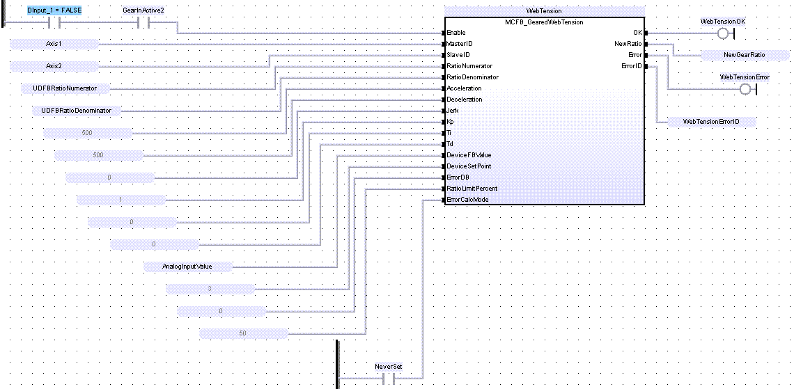
FBD Language Example
FFLD Language Example
IL Language Example
Not available.
ST Language Example
Inst_MCFB_GearedWebTension( DInput_1, Axis1, Axis2,
    ratioNumerator, ratioDenominator, 500.0, 500.0, 0.0, 1.0, 0.0, 0.0,
    AnalogInputValue, 3.0, 0.0, 50.0, NeverSet);
WebTensionOK       := Inst_MCFB_GearedWebTension.OK;
NewGearRatio       := Inst_MCFB_GearedWebTension.NewRatio;
WebTensionHasError := Inst_MCFB_GearedWebTension.Error;
WebTensionErrorID  := Inst_MCFB_GearedWebTension.ErrorID;
See Also


