![]()
 Function
![]() A function calculates a result according to the current value of its inputs. A function has no internal data and is not linked to declared instances. - Initializes a sampler object.
A function calculates a result according to the current value of its inputs. A function has no internal data and is not linked to declared instances. - Initializes a sampler object.
Inputs
|
Input |
Data Type |
Range |
Unit |
Default |
Description |
|---|---|---|---|---|---|
|
BlockID |
DINT |
-2147483648 to 2147483647 |
N/A |
No default |
ID Name of the SMP function block in the Pipe Network. |
|
SamplingPeriod |
LREAL |
0.25 to ? |
Millisecond |
1.0 |
Period that the device is sampled. |
|
Mode |
DINT |
1, 2 Position or Speed |
N/A |
Position |
Sampled output can be either Position or Velocity. |
|
InputModuloPosition |
LREAL |
No range |
User units |
360.0 |
Period of the input signal. The value set depends upon the device used.
|
|
OutputModuloPosition |
LREAL |
No range |
User units |
360.0 |
Period of the output signal. |
Outputs
|
Output |
Data Type |
Range |
Unit |
Description |
|---|---|---|---|---|
|
Default (.Q) |
BOOL |
|
N/A |
SMP Block successfully initiated. See Pipe Network - General Rules for more information. |
Remarks
- This sampler block is used to periodically sample and place into a pipe some output of a source object.
- The sampled output can be the POSITION or SPEED of a source object measured by a resolver, an encoder, or some other types of sensor
 A sensor is a type of transducer that converts one type of energy into another for various purposes including measurement or information transfer.
- The sampled output can be the POSITION or SPEED of a source object measured by a resolver, an encoder, or some other types of sensor
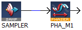
- The sampler implements the logical connection between:
- An encoder on a physical master axis (the source object).
- One or more pipes.
- It performs the function of periodically sampling the source and placing the sampled values into the pipe.
- This function block is automatically called by the Function PipeNetwork(MLPN_CREATE_OBJECTS) if a Smp Block is added to the Pipe Network, with user-defined settings entered in the Pipe Blocks Properties screen.
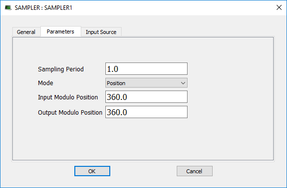
- The Smp Pipe Block is assigned a Name, SAMPLING_PERIOD, MODE, INPUT_VALUE_PERIOD, and OUTPUT_VALUE_PERIOD.
- This function can be programmed from within the Pipe Network block.
Right-click the block and click Properties.
- To offset the Sampler Block Output Position in the Pipe Network either:
- Place a Phaser Block (and write MLPhaWritePhase in the application code).
- Place a Gear Block (and write MLGearWriteOff ) after the Sampler Block.
|
Using AKD Secondary Feedback |
Using AKD2G Additional Feedback |
|---|---|
|
|
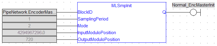
FBD Language Example
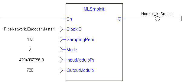
FFLD Language Example
IL Language Example
Not available.
ST Language Example
//Initialize  a Sampler Pipe Block named “EncoderMaster1” to a Sample Period of 1 millisec, Mode of Operation to 2(Velocity), Input Modulo of 4294967296, and Output Modulo of 720
MLSmpInit( PipeNetwork.EncoderMaster1, 1.0,2,4294967296,720);
See Also


