Coordinated Motion - 3-Axis Template
This project controls two axes in coordinated motion (PLCOpenAxis1 and PLCOpenAxis2), and a third independent axis (VERTICAL_AXIS).
This template demonstrates how to use coordinated motion PLCopen![]() A vendor -and product- independent worldwide association active in Industrial Control and aiming at standardizing PLC file formats based on XML axes and a Pipe Network axis.
A vendor -and product- independent worldwide association active in Industrial Control and aiming at standardizing PLC file formats based on XML axes and a Pipe Network axis.
PLC Programs
The Coordinated Motion 3-Axis template has a Sequential Function![]() A function calculates a result according to the current value of its inputs. A function has no internal data and is not linked to declared instances. Chart (SFC
A function calculates a result according to the current value of its inputs. A function has no internal data and is not linked to declared instances. Chart (SFC![]() "Sequential Function Chart"
It can be used to program processes that can be split into steps.
The main components of SFC are:
- Steps with associated actions
- Transitions with associated logic conditions
- Directed links between steps and transitions) program containing both Structured Text (ST
"Sequential Function Chart"
It can be used to program processes that can be split into steps.
The main components of SFC are:
- Steps with associated actions
- Transitions with associated logic conditions
- Directed links between steps and transitions) program containing both Structured Text (ST![]() "Structured text"
A high-level language that is block structured and syntactically resembles Pascal) and Free Form Ladder Diagram (FFLD
"Structured text"
A high-level language that is block structured and syntactically resembles Pascal) and Free Form Ladder Diagram (FFLD![]() "Free Form Ladder Diagram") code.
"Free Form Ladder Diagram") code.
- Steps 1 to 5 of the SFC program create and initialize the axes and the coordinated motion axes group plus the Pipe Network axis.
- Step 6 of the SFC interfaces with the Control Panel and performs a back-and-forth coordinated motion pattern with the two axes.
- The program utilizes coordinated motion direct moves, linear moves, circular moves, transitions and blending.
- It performs basic moves for the third (Pipe Network) axis, to move down/up before and after the coordinated motion pattern.
Motion Procedure
This template uses both motion engines (Pipe Network and PLCopen) simultaneously.
-
-
Coordinated motion can only be performed with PLCopen axes, Pipe Network axes do not support this feature.
PLCopen axes that perform coordinated motion can be mixed with independent Pipe Network axes.There is no axis synchronization at the Motion Engine level between a PLCopen axis and a Pipe Network axis.
Any synchronization between the axes must be performed inside the PLC
 "Programmable Logic Controller"
A Programmable Logic Controller, PLC, or Programmable Controller is a digital computer used for automation of industrial processes, such as control of machinery on factory assembly lines.
Used to synchronize the flow of inputs from (physical) sensors and events with the flow of outputs to actuators and events application.
"Programmable Logic Controller"
A Programmable Logic Controller, PLC, or Programmable Controller is a digital computer used for automation of industrial processes, such as control of machinery on factory assembly lines.
Used to synchronize the flow of inputs from (physical) sensors and events with the flow of outputs to actuators and events application.
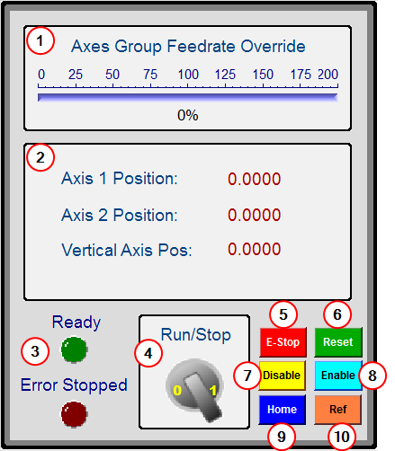
- Download and start the application.
- Press the Enable button to enable the axes and the axes group.
- Optional: Press the Home button to move the axes to their zero position.
- When the Ready light is on, turn the Cycle Start switch to 1.
The axes begin moving in the programmed pattern.
Control Panel
|
# |
Description |
GUI |
|---|---|---|
|
|
Used to change the coordinated motion feedrate from 0% to 200%. |
|
|
|
Displays the axis positions. |
|
|
|
Indicator lights.
|
|
|
|
Begins the coordinated motion pattern. |
|
|
|
|
|
|
|
|
|
|
|
Disables the axes or axes group. |
|
|
|
Enables the axes and the axes group. |
|
|
|
Moves all axes or axes group to their zero position. |
|
|
|
Causes a reference by setting the axes' position to zero at their current location. |