 Current Loop
Overview
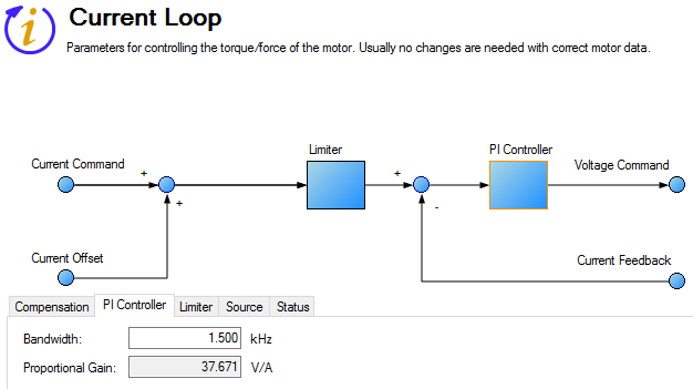
The current loop controls the production of current on each axis. The parameters that govern the current loop are shown in the Current Loop view. The various types of tuning for the drive adjust these parameters automatically, so you normally do not need to adjust the current loop parameters in the current loop screen. The Current Loop view includes an active block diagram. If you click on a block in the diagram, the appropriate tab opens below.
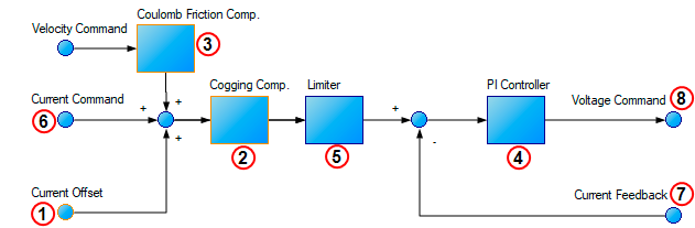
Tabs in the Current Loop View
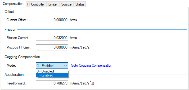
Compensation Tab – items found here are a part of blocks #1, #2 and #3 above
| Element | Property | Description | Parameter |
|---|---|---|---|
| Offset | Current Offset | A constant current command added to compensate for gravity. | AXIS#.IL.OFFSET |
| Friction | Frictio Current | This is a friction compensation value. | AXIS#.IL.FRICTION |
| Viscous FF Gain | Current loop velocity feed-forward |
AXIS#.IL.KVFF | |
| Cogging Compensation | Mode | Removes the effects of cogging (magnetic forces) between the motor's permanent magnets and windings and repeatable artifacts from bearings, leadscrews, and other mechanical components. | AXIS#.IL.COMPTABLE.ENABLE |
| Acceleration | Feedforward | Sets the gain for the acceleration feedforward (a scaled second derivative of the position command is added to the current command value) | AXIS#.IL.KACCFF |
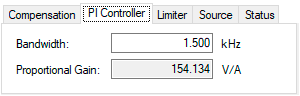
PI Controller Tab – items found here are calculated in block #4 above (Also see Current Loop Gain )
| Property | Description | Parameter |
|---|---|---|
| Bandwidth |
Sets the current loop bandwidth |
AXIS#.IL.BW |
| Proportional Gain | Gets the proportional gain of the q-component of the PI regulator. This is a read-only value. | AXIS#.IL.KP |
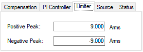
Limiter Tab – items found here are calculated in block #5 above
| Property | Description | Parameter |
|---|---|---|
| Positive Peak | Sets the positive user (application-specific) current limit. | AXIS#.IL.LIMITP |
| Negative Peak | Sets the negative user (application-specific) current limit. | AXIS#.IL.LIMITN |
Source Tab - Feedback Selection
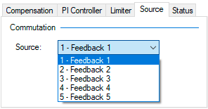
| Element | Property | Description | Parameter |
|---|---|---|---|
| Commutation | Source | Tells the drive which feedback the Current Loop is using for commutation. | AXIS#.IL.FBSOURCE |
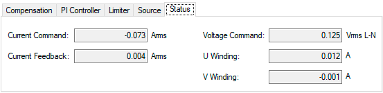
Status Tab – items found here are calculated in blocks #6, #7, #8 above
| Property | Description | Parameter |
|---|---|---|
| Current Command | Reads the value of the q-component current command. | AXIS#.IL.CMD |
| Current Feedback | Reads the actual value of the q-component current. | AXIS#.IL.FB |
| Voltage Command | Reads the output of the q-component PI regulator. | AXIS#.IL.VCMD |
| U Winding | Reads the sigma-delta measured current in the U-winding of the AXIS#.MOTOR. | AXIS#.IL.IUFB |
| V Winding | Reads the sigma-delta measured current in the V-winding of the AXIS#.MOTOR. | AXIS#.IL.IVFB |
Current Loop Gain
The current loop bandwidth is defined by AXIS#.IL.BW. In most applications the default bandwidth value is acceptable.
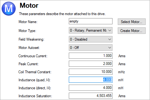
The current loop gain AXIS#.IL.KP is based on the bandwidth and the motor inductance:
AXIS#.IL.KP = 2 * pi * AXIS#.MOTOR.LQLL * AXIS#.IL.BW.
Where AXIS#.MOTOR.LQLL is the motor line-to-line inductance.
The current loop gain is set automatically by the drive. The inductance used in the calculation is determined using one of the following methods:
- Option A. When AXIS#.MOTOR.AUTOSET = 1 and motor parameters are automatically identified on the AXIS#.IL.FBSOURCE feedback device
 A process whereby some proportion of the output signal of a system is passed (fed back) to the input.
In automation, a device coupled to each motor to provide indication of the motor's shaft angle, for use in commutating the motor and controlling its speed and position, the proportional gain of the current loop (AXIS#.IL.KP ) is set based on AXIS#.MOTOR.LQLL
read from motor memory. The gain is shown as a read-only parameter in the current loop screen.
A process whereby some proportion of the output signal of a system is passed (fed back) to the input.
In automation, a device coupled to each motor to provide indication of the motor's shaft angle, for use in commutating the motor and controlling its speed and position, the proportional gain of the current loop (AXIS#.IL.KP ) is set based on AXIS#.MOTOR.LQLL
read from motor memory. The gain is shown as a read-only parameter in the current loop screen. - Option B.When the motor is selected using the motor database or using the custom motor tool, the specified Inductance (quad) value (AXIS#.MOTOR.LQLL
) is used to set the current loop proportional gain (AXIS#.IL.KP ).
Related Parameters


