FB_FirstOrderDigitalFilter
 Function Block - Defined to filter an Analog signal.
Inputs
|
Input |
Data Type |
Range |
Unit |
Default |
Description |
|---|---|---|---|---|---|
|
EN |
BOOL |
No range |
N/A |
No default |
Enables execution. Used in the FFLD editor only. |
|
AnalogInput |
INT |
No range |
N/A |
No default |
Analog Input from transducer. |
|
FilterGain |
REAL |
1 - 0.05 |
N/A |
No default |
Filter gain. |
Outputs
|
Output |
Data Type |
Range |
Unit |
Description |
|---|---|---|---|---|
|
OK |
BOOL |
0, 1 |
N/A |
Execution successful. |
|
FilterOutput |
REAL |
0, 1 |
N/A |
Filtered analog input value. |
Remarks
In any control system with an analog feedback signal present, there is the risk of unwanted noise and jitter that can compromise the signal integrity yielding a less the desirable system.
- This Kollmorgen UDFB provides a digital first order filter of an analog feedback signal from an LVDT, tension transducer, potentiometer, encoder, resolver, or some other like device.
- The amount of filtering is based on a gain value and can provide no filter to full filter conditioning.
This image shows the function or function block I/O.
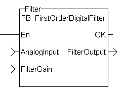
Figure 1: CBS First Order Digital Filter
Usage
When using this UDFB, the Enable (EN) input should always be energized to provide the desired filtering.
- The AnalogInput input is the unfiltered analog feedback signal from an LVDT, tension transducer, potentiometer, or some other like device.
- The FilterGain defines the amount of filtering to be used.
- The range of the gain is from 1.0 or no filtering to 0.05 or the maximum filtering.
- The FilterOutput is the filtered analog input.
- It is used as an input to some other function block or UDFB that has an analog input (e.g., the MCFB_GearedWebTension UDFB).
- The implementation of the digital first order filter is for PLCopen.
- The equation is defined as:
Input*Gain+Output*(1-Gain) = Output. - The steady state filter delay with a gain of 0.8 is shown in the Filter Input Delay table.
Filter Input Delay
|
FilterGain |
FilterInput |
FilterOutput |
|---|---|---|
|
0.8 |
0 |
0 |
|
|
100 |
80 |
|
|
100 |
96 |
|
|
100 |
99.2 |
|
|
100 |
99.84 |
|
|
100 |
99.968 |
|
|
100 |
99.9936 |
|
|
100 |
99.99872 |
|
|
100 |
99.999744 |
|
|
100 |
99.9999488 |
|
|
100 |
99.99998976 |
|
|
100 |
99.99999795 |
|
|
100 |
99.99999959 |
|
|
100 |
99.99999992 |
|
|
100 |
99.99999998 |
|
|
100 |
100 |
|
|
100 |
100 |
|
|
100 |
100 |
|
|
100 |
100 |
|
|
100 |
100 |
|
|
100 |
100 |
|
|
100 |
100 |
|
|
100 |
100 |
Filter Delay Tn
In this table:
- The numbers of filter delays for a steady state analog input at a given gain are listed.
- The range of the filter gain is between 1.00 and 0.05.
- For a filter gain of 0.8 there is a delay of 15 time constants with a time constant defined as the rate the UDFB is scanned or executed in the application.
- Example: If the UDFB was executed every millisecond a gain of 0.8 would provide a filter delay of 15ms.
- Conversely a gain of 1.00 provides zero filtering and the output signal follows the input signal, and a gain of 0.05 provides the most filtering for 463 ms.
|
Gain |
Filter Delay Tn |
Graph |
|---|---|---|
|
1.00 |
0 |
|
|
0.95 |
8 |
|
|
.90 |
11 |
|
|
.85 |
13 |
|
|
.80 |
15 |
|
|
.75 |
18 |
|
|
.70 |
20 |
|
|
.65 |
23 |
|
|
.60 |
26 |
|
|
.55 |
30 |
|
|
.50 |
35 |
|
|
.45 |
40 |
|
|
.40 |
47 |
|
|
.35 |
56 |
|
|
.30 |
66 |
|
|
.25 |
83 |
|
|
.20 |
107 |
|
|
.15 |
146 |
|
|
.10 |
226 |
|
|
.05 |
463 |

Example: Filter Input Lag - Random Input
A real world analog input is most always a varying feedback signal.
In this table, an initial input of 100, a gain of 0.8, and a random variability of 10%.Filter Input
|
Filter Input |
Filter Current Output |
Amount of Input Filtering |
Random Filter % Variation |
|---|---|---|---|
|
0 |
0 |
0 |
10% |
|
100 |
80 |
-20 |
|
|
97.38903813 |
93.9112305 |
-3.477807626 |
|
|
92.67638093 |
92.92335084 |
0.246969915 |
|
|
94.12988912 |
93.88858146 |
-0.241307655 |
|
|
103.0835564 |
101.2445614 |
-1.838994993 |
|
|
91.16845433 |
93.18367575 |
2.015221422 |
|
|
93.23936976 |
93.22823096 |
-0.011138803 |
|
|
94.90272089 |
94.56782291 |
-0.334897986 |
|
|
103.3070737 |
101.5592235 |
-1.747850153 |
|
|
96.83149418 |
97.77704005 |
0.945545867 |
|
|
96.35024002 |
96.63560002 |
0.285360007 |
|
|
99.82417525 |
99.1864602 |
-0.637715045 |
|
|
105.0792636 |
103.9007029 |
-1.178560685 |
|
|
97.36988208 |
98.67604626 |
1.306164172 |
|
|
107.82502 |
105.9952253 |
-1.829794752 |
|
|
97.7886524 |
99.42996698 |
1.641314572 |
|
|
108.2038024 |
106.4490353 |
-1.754767081 |
|
|
91.58527607 |
94.55802792 |
2.972751845 |
|
|
93.6783421 |
93.85427926 |
0.175937164 |
|
|
102.8695349 |
101.0664838 |
-1.803051129 |
|
|
93.95916817 |
95.3806313 |
1.421463121 |
|
|
108.6579707 |
106.0025028 |
-2.655467871 |
|
|
109.3425748 |
108.6745604 |
-0.668014397 |
|
|
103.9066 |
104.8601921 |
0.953592077 |
|
|
92.30112142 |
94.81293555 |
2.511814127 |
|
|
109.4460726 |
106.5194452 |
-2.926627416 |
|
|
94.88799896 |
97.21428821 |
2.326289251 |
|
|
105.4738635 |
103.8219484 |
-1.651915057 |
|
|
102.988167 |
103.1549233 |
0.166756284 |
|
|
92.92925408 |
94.97438792 |
2.045133846 |
|
|
95.58185568 |
95.46036213 |
-0.121493552 |
|
|
109.414248 |
106.6234708 |
-2.790777178 |
|
|
106.5661311 |
106.577599 |
0.011467953 |
|
|
99.85857253 |
101.2023778 |
1.343805301 |
|
|
107.865421 |
106.5328124 |
-1.332608643 |
|
|
92.19683177 |
95.0640279 |
2.867196126 |
|
|
104.8558146 |
102.8974573 |
-1.958357346 |
|
|
104.5140236 |
104.1907104 |
-0.323313268 |
|
|
104.3675014 |
104.3321432 |
-0.035358206 |
|
|
109.2704266 |
108.2827699 |
-0.987656683 |
|
|
101.4962729 |
102.8535723 |
1.35729941 |
|
|
92.19199163 |
94.32430776 |
2.132316128 |
|
|
99.13065312 |
98.16938405 |
-0.961269073 |
|
|
103.5068114 |
102.4393259 |
-1.067485466 |
|
|
109.502983 |
108.0902516 |
-1.412731426 |
|
|
99.05504822 |
100.8620889 |
1.80704068 |
|
|
94.97711299 |
96.15410817 |
1.176995182 |
|
|
107.1063597 |
104.9159094 |
-2.190450308 |
|
|
91.12245188 |
93.88114339 |
2.758691504 |
|
|
108.130314 |
105.2804799 |
-2.849834129 |
|
|
104.2923832 |
104.4900025 |
0.197619344 |
|
|
101.3775072 |
102.0000062 |
0.62249907 |
|
|
100.5303014 |
100.0399168 |
-0.490384645 |
Averages |
FBD Language Example

FFLD Language Example

IL Language Example
Not available.
ST Language Example
//Filter analog input signal with a gain of 0.8 to remove noise
FilteredOutput:= Inst_FB_FirstOrderDigitalFilter( AnalogInput1Value, 0.8 );


