EtherNet/IP Adapter (Server)
The KAS Runtime includes fully integrated EtherNet/IP server driver for exchanging CIP I/O assemblies as an EtherNet/IP adapter in your applications.
Data Exchange - Configuration
A dedicated configuration tool is integrated in the KAS-IDE.
- Double-click the Fieldbus node in the project explorer to open it.
- Click the Insert Configuration icon
 to add the Fieldbus configuration.
 - Select the EtherNet/IP Adapter in the configuration selector.

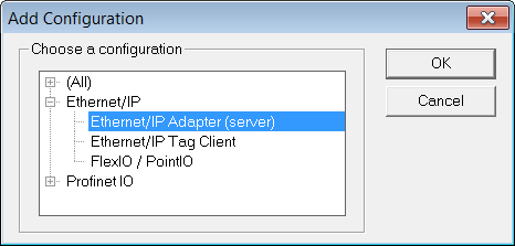
The configuration is represented as a tree:
- EtherNet/IP I/O Scanner
- Served I/Os and objects
- I/O Assembly or Vendor Specific Object (*)
- Exchanged Variable (*)
- I/O Assembly or Vendor Specific Object (*)
(*) The items with this mark can appear several times in the configuration.
- Served I/Os and objects
Configuration
These items can be configured at the root level:
|
Identifier |
Meaning |
|---|---|
|
Use LAN2 |
Obsolete |
|
IP Address |
IP address of the Ethernet adapter used. |
Click the Insert Master icon  to declare a server (adapter device).
Each server is identified by its IP address and an optional Description text.
Select the Served I/Os and objects node, then click the Insert Slave icon  to declare a CIP I/O assembly or a vendor specific object. Up to 4 input and 4 output assemblies are supported by the KAS Runtime, even though it is possible to create more in the KAS-IDE.
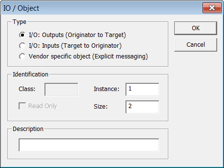
Each assembly is identified by:
|
Identifier |
Meaning |
|---|---|
|
Mode |
The kind of CIP object. Either:
|
|
Access |
In case of a vendor specific object, this property defines the access rights:
|
|
Class |
CIP class in case of a vendor specific object. This field should be ignored in case of an I/O assembly. |
|
Instance |
Instance of the CIP assembly or object. |
|
Size |
Data size in bytes. |
|
Read Only |
Specify that a vendor-specific object is only readable by clients. |
|
Description |
Optional description text. |
When defining a vendor specific objects, these attributes are available for scanners:
- 1 (get only) = size of the object data.
- 3 (get/set) = object data.
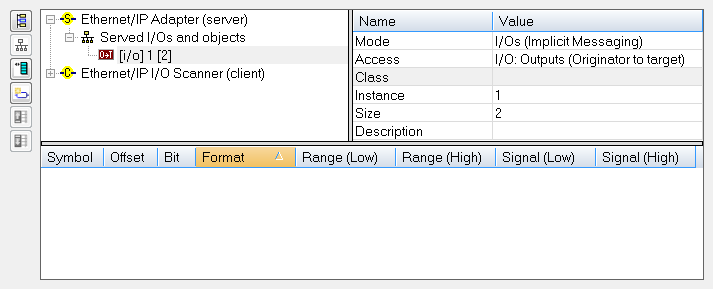
Then map IEC 61131-3 variables on the data of the assembly, for each variable you must specify:
|
Identifier |
Meaning |
|---|---|
|
Symbol |
The name of the IEC 61131-3 variable |
|
Offset |
Offset in bytes in the assembly data |
|
Bit |
Bit offset in the selected byte if format is "Bit" |
|
Format |
Format of the data in the assembly |
-
-
Drag a variable from the Dictionary directly to a slave item.
-
-
The data limit is:
500 bytes of data maximum O(originator)->T(target) and
500 bytes of data maximum T(target) -> O(originator).
This is based on the EtherNet/IP specification.


