EtherNet/IP Tag Client
The KAS Runtime includes fully integrated EtherNet/IP client driver for exchanging tags with EtherNet/IP tag based devices such as PLCs.
Data exchange - Configuration
A dedicated configuration tool is integrated in the KAS-IDE.
- Double-click the Fieldbus node in the project explorer to open it.
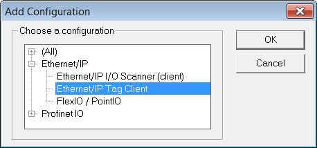
- Click the Insert Configuration icon
 to add the Fieldbus configuration.
 - Select the EtherNet/IP Tag Client in the configuration selector.
The configuration is represented as a tree:
- EtherNet/IP Tag Client
- Server (an EtherNet/IP adapter device) (*)
- Tag (generally an array) (*)
- Exchanged variable (*)
- Exchanged variable (*)
- Tag (generally an array) (*)
(*) The items with this mark can appear several times in the configuration.
- Server (an EtherNet/IP adapter device) (*)
Driver and configurator are optimized for exchanging arrays (tags declared as arrays in the PLC). However it is also possible to exchange single tags.
Configuration
Click the Insert Master icon  to declare an server (slave device). Each server is identified by its IP address and an optional description text.
Then you need to configure tags such as declared in the PLC:
- The easiest way is to right-click on the server in the tree and select the Add ARRAY Tag command in the contextual menu. Then you enter the properties of the tag request and the symbol of the corresponding array to be used in your IEC 61131-3 application. Configuration of the tag and mapping of all array items is performed automatically.
- Alternatively, click the Insert Slaver icon
 to declare the tag and map some variables later on.
A tag request is identified by:
|
Identifier |
Meaning |
|---|---|
|
Tag name |
The name of the tag such as declared in the PLC. |
|
PLC Slot |
PLC slot number. |
|
Mode |
Read or Write. The same tag can be configured twice for both reading and writing. |
|
Nb Elements |
Number of array items to read or write. |
|
Offset |
O-based index of the first item to read or write in the array. |
|
Tag data type |
Data type of the tag such as declared in the PLC. Available Types are:
|
|
Period(ms) |
Specify in this parameter a period for continuously sending the request. Enter 0 (zero) for a request sent on-demand. |
|
Timeout |
Request timeout in milliseconds. |
IEC 61131-3 variables are mapped on the data of the tag.
For each variable you must specify:
|
Identifier |
Meaning |
|---|---|
|
Symbol |
The name of the IEC 61131-3 variable. |
|
Offset |
Offset in bytes in the assembly data. |
|
Bit |
Bit offset in the selected byte if format is Bit. |
|
Format |
Format of the data in the assembly. |
|
Mode |
The kind of data exchanged through the variable:
|
The tag is read or written:
- Periodically if a non zero period is specified in the tag configuration.
- When a variable configured as Send Request Now becomes TRUE.
In the case of a command variable, the variable is automatically reset to FALSE when the request is sent.
-
-
The data limit is:
500 bytes of data maximum O(originator)->T(target) and
500 bytes of data maximum T(target) -> O(originator).
This is based on the EtherNet/IP specification.


