Modbus Slave
The KAS Runtime includes fully integrated slave functions for enabling Modbus communication on a serial link or Ethernet.
This communication is done in the background, asynchronously, at the cycle time (20-1000 milliseconds) specified in the Controller Properties. See Configure the Controller for more information.
- Variables defined in the HMI to describe the interface are passed to the controller this way.
- See Map Variables to HMI for more information.
- This means there is no data coherency in the data exchange because the variables read by the Modbus do not come from the same PLC cycle.
- This data has a rather low priority.
- It is interpreted by human feedback and should never be noticed by the user.
-
-
Kollmorgen HMIs are limited to communicating no more frequently than every 100 milliseconds.
-
-
It is possible to have two Modbus master devices communicating with a controller at the same time, accessing the same variables.
Example: Having two separate HMI panels running the same program on a single, large machine.
Protocol Specification
The protocol supported is Open Modbus on Ethernet.
These are the supported Modbus function codes:
|
Code |
Description |
|---|---|
|
1 |
Read coils. |
|
2 |
Read bit inputs. |
|
3 |
Read holding registers. |
|
4 |
Read input registers. |
|
5 |
Write 1 coil. |
|
6 |
Write 1 register. |
|
15 |
Write n coils. |
|
16 |
Write n registers. |
- As a default, the first valid address for each kind of data is 1.
- If you use Modbus devices with other addressing conventions, you can change the base offset for each kind of data using the Tools > Addresses menu command.
Data Exchange Configuration
The KAS-IDE has a dedicated configuration tool. To run it,
- In the Controller Properties dialog box, select the Other Modbus devices option.
See Configure the Controller for more information. - Double-click the Fieldbus node in the project explorer to open it
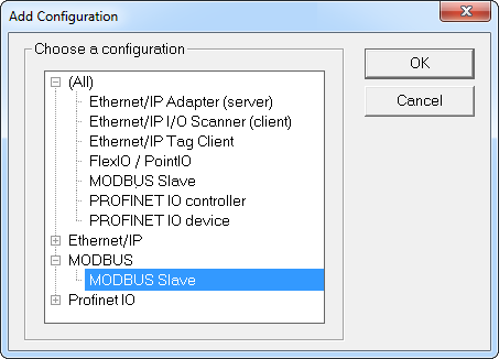
- Click the Insert Configuration icon to add the Fieldbus configuration.
- Select the Modbus Slave in the configuration selector.
- Click OK to continue.
The Modbus Slave configuration is represented as a tree:
- Modbus Slave
- Slave number (variables that can be accessed from external Modbus masters)
- Input bits data block (read by masters)
- Variable (*)
- Input words data block (read by masters)
- Variable (*)
- Coil bits data block (forced by masters)
- Variable (*)
- Holding bits data block (forced by masters)
- Variable (*)
- Input bits data block (read by masters)
(*) The items with this mark can appear several times in the configuration.
- Slave number (variables that can be accessed from external Modbus masters)
Modbus Slave Configuration
You need to configure the Modbus Slave to make variables visible from external Modbus masters (e.g., SCADA systems).
This is a simple example of slave configuration: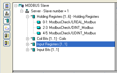
- Double click the Server item to setup the Modbus slave number that will identify the runtime application.
- When the local server is selected, use the Insert Slave/Data Block menu command to insert Modbus data blocks.
- These kinds of block are available:
-
-
For optimal controller performance use Input Registers where possible.
Input Registers require 15-25% less CPU time to exchange data than Holding Registers do.
Each data block is identified by a Modbus base address and a number of items (bits or words).
-
-
Read and write requests sent by Modbus masters are denied if the range specified in the request does not fit within a data block defined in the configuration.
Requests overlapping two data blocks are denied.
Example: If you configure a block of 16 words starting at address 1 and another block of 16 words starting at address 17, a request for read or write of 32 words starting at address 1 is denied and an address error exception is reported.
When a server data block is selected, use the New symbol command to map a variable to an item of the data block.
Each variable is identified by a valid symbol of a variable in the open project and an offset in the data block according to Modbus addressing.
Exchanges
- For exchanging:
- Boolean variables through Modbus words, a hexadecimal mask is available to define to which bit of a word a variable is attached.
- Example: Enter the mask 0001 to map a Boolean variable to the less significant bit of a word.
- 32-bit variables (e.g., DINT, REAL, etc.), select to map the variable on two consecutive words.
64-bit variables(e.g., LINT, LREAL, LWORD, ULINT), select to map the variable on four consecutive words
- Boolean variables through Modbus words, a hexadecimal mask is available to define to which bit of a word a variable is attached.
Optional: Sort the variables of each data block according to their offset using the Sort symbols menu command at any time.
Data Types
You can freely map a variable of any data type to a Modbus item.
The Runtime automatically converts the value to the type of the variable.


