Distributed Clock tab
This tab is used to change settings related to the Distributed Clock for all Kollmorgen and third-party devices (both discovered and manually added).
|
Element |
Description |
|---|---|
|
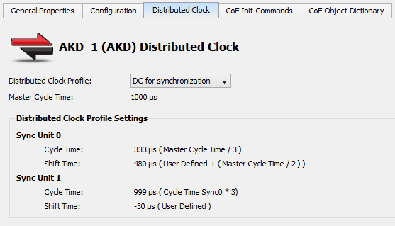
Distributed Clock Profile |
Select the Distributed Clock (DC) operation mode. These modes cannot be edited.
|
|
Master Cycle Time |
Base interval in microseconds and is used by the master. This is changed and automatically updated by changing the Cycle Time value on the EtherCAT Master Settings tab tab. |
|
Sync Unit 0 |
Cycle Time:
Shift Time:
|
|
Sync Unit 1 |
Cycle Time:
Shift Time:
|
-
-
Some or none of the content will be available under the following scenarios:
- The Sync 0 or Sync 1 parameter is not present
- Distributed Clock is not supported by the device
- The ESI file is missing.
Oversampling devices
Some EtherCAT devices have oversampling features.
- An oversampling device is able to record (input) or provide (output) signals at a higher rate than the EtherCAT cycle time.
- This rate is called the oversampling factor.
- Example: Using an oversampling factor of 10 and an EtherCAT cycle time of 1ms (1Khz), an input device can record values every 100µs (1000 divided by 10).
Oversampling devices have as many PDO objects in their cyclic frames as the oversampling factor to achieve the higher rate.
- Each of these PDO objects corresponds to one sample.
- Example: An output device with an oversampling factor of 4 has four PDO objects:
- Output 1, Output 2, Output 3 and Output 4.
The oversampling factor is tied to the Distributed Clock Profile.
A warning appears next to the DC profile selection box in the Distributed Clocks tab when a device has oversampling features:
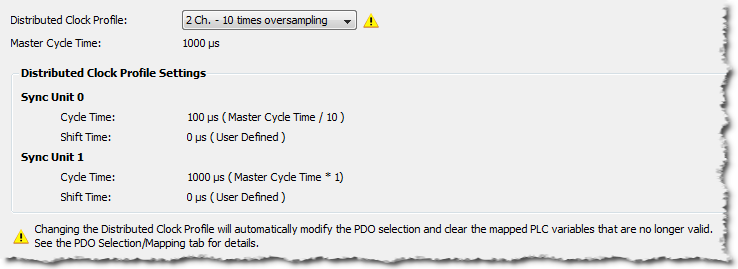
Figure 1: Example of a device with oversampling.
Changing the Distributed Clock Profile automatically changes the PDO selection.
- All PDOs corresponding to the selected Distributed Clock Profile and its according oversampling factor are selected.
- These maps are discarded if one or several PLC variables were mapped to a PDO that is no longer selected.


