ENI File tab
During the compilation, the KAS-IDE generates the EtherCAT Network Information (ENI) file based on the EtherCAT devices defined in the project.
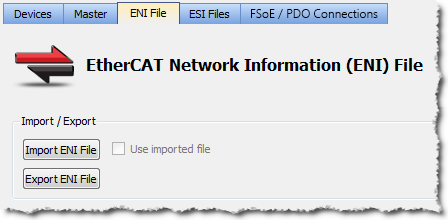
Figure 1: ENI File tab
Import or Export an EtherCAT ENI File
|
Item |
Description |
|
Used to browse and select an ENI file to be imported.
|
|
|
Use imported ENI file |
Used to specify whether or not to use the imported ENI file. |
|
Used to export the ENI file generated by the KAS-IDE.
|
-
-
Importing an external ENI file overrides all EtherCAT project device information and configuration settings in the KAS-IDE.
These views and configurations are not applicable when using an imported ENI file:
- Project View: All devices located under the EtherCAT node.
- EtherCAT Device View tabs:
- General Properties
- PDO Selection/Mapping
- Distributed Clock
- CoE Init-Commands
- Slice I/O Properties
- Mapping PLC Variables to Slice I/O or PDO objects.
Information displayed in the views may not match the imported ENI file.
Use an Imported ENI File
- The KAS-IDE works in a degraded mode when using an imported ENI file, and the Mapped to Axis settings are disabled.
- This is because the information about the devices in the project tree and the EtherCAT widget table is no longer relevant.
- When using an imported configuration file these parameters must be manually set for each axis:
- the type of motion bus.
- its address on the fieldbus ring.
This is done by right-clicking on the Axis Pipe Block and selecting the Properties command.
- Scan Devices must be run from the EtherCAT Devices tab before downloading the application to the controller.


