Main Module Implementation
In the main module, all necessary state, state transition, error and function handling facilities are implemented for this level.
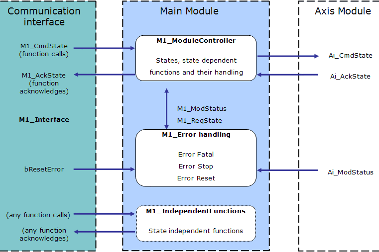
Figure 1: Context Diagram for Main Module
These objects (variables, tasks...) are defined in the structure of the main module.
bErrorReset
This internal flag variable is used as the error reset command for the main and axis modules. It is reset during power up.
Usage
- Set and reset this flag to activate a reset of the module errors (M1_StatusWord, Ai_StatusWord).
M1_AckState
This internal word variable contains the actual state acknowledge value, as a result from the M1_CmdState state command performed with success.
- Possible values are the same as for the state commands.
- See M1_CmdState.
Usage
- The corresponding acknowledgments for the PLC can be created in the communication interface.
M1_CmdState
This internal word variable contains the actual state command value.
It is automatically set to state Standby during power up.
//*********************************************
//**             State Defines               **
//*********************************************
#define DEF_StateUndefined                    0
#define DEF_StateStandby                      1
#define DEF_StateManual                       2
#define DEF_StateAutomatic                    3
#define DEF_StateBusy                         4
#define DEF_StateErrorStop             5
#define DEF_StateErrorFatal                   6
Usage
- State commands are usually set in the communication interface (see software listing of ACT_M1_Translate and ACT_M1_SimaticSimu) and must not be set directly from the host system.
- If additional or different state commands are needed, the definitions can be modified.
M1_ErrorHandling
This program is responsible for the main module error handling.
- If an error occurs (in the main module or a submitted axis module), the corresponding bit in the module status (M1_StatusWord) is set.
- This causes the error reaction bits (MSK_Mi_StatusErrorStop, MSK_Mi_StatusErrorFatal) to be set in the module status word.
Usage
- Any additional error which needs to be treated has to be included in this program.
- Remember to modify the corresponding masks (MSK_M1_StatusErrorFatal, MSK_M1_StatusErrorStop) to cause the correct reaction on errors.
M1_ModStatus, (Ai_ModStatus)
This internal word variable contains the actual module status and error information.
- It is automatically set to the default value during power up.
- The meaning of the predefined Module Error Bits are:
|
Bit |
Description |
|
0 |
Error stop reported by drive (drive error). |
|
1 |
Error fatal reported by Drive (lag error). |
|
2 |
Not used (motor temperature too high). |
|
3 |
Not used (external stop). |
|
4 |
Not used (negative limit switch reached). |
|
5 |
Not used (positive limit switch reach). |
|
6 |
Not used (not used). |
|
7 |
Not used (not used). |
|
8 |
Not used (state HW enable) |
|
9 |
Not used (state AS enable). |
|
10 |
Not used (axis is powered on). |
|
11 |
Not used (axis is homed). |
|
12 |
Not used (axis is running). |
|
13 |
Not used (pipe is connected). |
|
14 |
Error stop (error stop). |
|
15 |
Error fatal (error fatal). |
Usage
- The error bits are usually set only by the error handling (M1_ErrorHandling).
- The mode bits can be modified where ever needed in the application program (except in the interface).
- Several bits can be set at the same time.
- Several masks have been defined to test or modify the whole word.
- For each module, there is one mask to define the bits causing a fatal error (e.g. MSK_M1_StatusErrorFatal) and one for the stop error (e.g. MSK_M1_StatusErrorStop).
- To add errors and modes, the bits not already assigned by default can be used (i.e. bits 16 to 31).
M1_ModuleController
This program is the heart of the whole controller and contains:
- A state manager sequence.
- All state sequences.
- State dependent function sequences of the main module.
Usage
- Some rules have to be followed when using and changing states and functions.
- See (➜ # 1, Add a New State) and (➜ # 1, Add a New Function) for more information.
M1_ReqState
This internal word variable contains the internally active state.
- It is used for internal purpose only, to keep the actual state value (e.g., while performing a function).
- Possible values are the same as for the state commands.
- See M1_CmdState.
- Possible values are the same as for the state commands.
Usage
- Used by system, do not use for application purposes.


