AKT2G-SM-L50-000
Stepper motor terminal, 50 V DC, 5 A, vector control
The AKT2G-SM-L50 EtherCAT Terminal is intended for stepper motors with medium performance range. The PWM output stages cover a wide range of voltages and currents. Together with two inputs for limit switches, they are located in the EtherCAT Terminal.
The SM-L50 can be adjusted to the motor and the application by changing just a few parameters. 64-fold micro-stepping ensures particularly quiet and precise motor operation. Together with a stepper motor and an encoder, the SM-L50 represents an inexpensive small servo axis.
The LEDs indicate status, warning and error messages as well as possibly active limitations.
Quick Links
- About Stepper Motors
- Standard Mode
- AKT2G-SM-Lx Object Description
- AKT2G-SM-Lxx PDO Assignment
- AKT2G-SM-Lxx Diagnostic Messages
- Mounting and Wiring of I/O Terminals
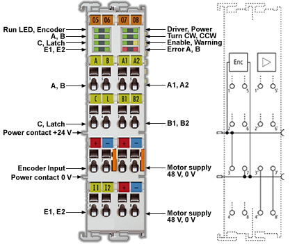
- AKT2G-SM-L50 LEDs and Connections
- AKT2G-SM-L50 General Connection Examples
Technical Data
| Technical Data | AKT2G-SM-L50 |
|---|---|
| Number of outputs | 1 stepper motor, 2 phases |
| Number of digital inputs | 2 limit position, 4 for an encoder system |
| Number of digital outputs | 1 configurable for brake (0.5 A) |
| Supply voltage | 8 … 50 V DC |
| Motor Current/Phase (RMS) values without fan cartridge ZB8610 | 3.53 A |
| Motor Current/Phase (RMS) values with fan cartridge ZB8610 | 4.59 A |
| Maximum output current without fan cartridge AKT2G-AC-FAN-001 | 5 A (overload- and short-circuit-proof) |
| Maximum output current with fan cartridge AKT2G-AC-FAN-001 | 6.5 A (overload- and short-circuit-proof) |
| Operating modes |
|
| Maximum step frequency | 1000, 2000, 4000, 8000 or 16000 full steps/s (configurable) |
| Step pattern | up to 64-fold micro stepping (automatic switching, speed-dependent) |
| Current controller frequency | approx. 30 kHz |
| Encoder pulse frequency | maximum 400,000 increments per second (4-fold evaluation) |
| Input signal voltage "0" | -3 V … 2 V |
| Input signal voltage "1" | 3.7 V … 28 V |
| Input Current | typ. 5 mA |
| Diagnostics LED | Warning strand A and B, error strand A and B, power, enable |
| Resolution | approx. 5,000 positions in typical applications (per revolution) |
| Power Supply | via the E-bus, encoder/driver stage: via the power contacts, motor: via terminal contacts |
| Current consumption from the E-bus | typ. 140 mA |
| Electrical isolation | 500 V (E-bus/signal voltage) |
| Support NoCoEStorage | yes |
| Configuration | no address setting required |
| Weight | approx. 105 g |
| Permissible ambient temperature range during operation | 0°C ... +55 °C |
| Permissible ambient temperature range during storage | -25°C ... + 85 °C |
| Permissible relative humidity | 95%, no condensation |
| Dimensions (W x H x D) | approx. 27 mm x 100 mm x 70 mm (connected width: 24 mm) |
| Installation | on 35 mm mounting rail according to EN 60715 |
| Vibration / shock resistance | conforms to EN 60068-2-6/EN 60068-2-27 |
| EMC immunity/emission | according to EN 61000-6-2 / EN 61000-6-4 according to IEC/EN 61800-3 |
| EMC category | Category C3 - standard Category C2, C1 - auxiliary filter required |
| Protection class | IP 20 |
| Installation position |
|
| Approval | CE cULus |


