Draw FBD Connection Lines

Click this button before inserting a new line.
-
-
The editor is used to terminate a connection line with a Boolean negation represented by a small circle:
(* use of a negated link: Q is IN1 AND NOT IN2 *)
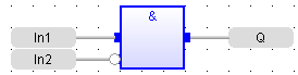
To set or remove the Boolean negation, select the line and press the <Spacebar>.
-
- The FBD editor automatically selects the best routing for the new line.
- Connection lines indicate a data flow between these possible objects:
|
Tool |
Button |
Description |
|---|---|---|
|
Block |
|
See the help for the block for the description of its input and output pins, and the expected data types for the coherence of the diagram. |
|
Coil |
|
A coil must be connected to a Boolean data flow from it's left-hand side. It is not mandatory that a coil be connected on its right-hand side. |
|
Contact |
|
A contact must be connected to a Boolean data flow on both its left- and right-hand side. |
|
Jump |
|
A jump must be connected to a Boolean data flow from its left-hand side. |
|
Left power rail |
|
Left power rails represent a TRUE state. It can be connected to an unlimited number of objects on their right-hand side. |
|
OR rail |
|
This type of rail collects several Boolean data flows for an "OR" operation, in order to insert parallel contacts (e.g., Ladder Diagrams).
|
|
Right power rail |
|
A right power rail is an element of the FFLD language, and is commonly used for terminating Boolean data flows.
|
|
Variable |
|
A variable can be connected on its right-hand side (to initiate a flow) or on their left-hand side to force the variable, if it is not read-only. The flow must fit the data type of the variable. |
-
-
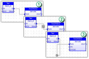
Connection lines automatically move and follow FBD elements (1) and you can also manually specify the corners.
Double-click on the line to show a handle (2) which can be repositioned (3).