Configure a PROFINET IO Controller
The IOs of the PROFINET network must be connected to the variables using a PROFINET IO controller.
The KAS-IDE contains a fully integrated configurator for a PROFINET IO RT controller or device.
The PROFINET maximum data size is 1440 bytes Input length and 1440 bytes Output length.
To calculate the size, use the slot configuration view to count the number of bits per slot and convert to bytes.
Example: 7 slots containing 16 outputs of 32-bits each, is 7 x 16 x 32 = 3584 bits = 448 bytes.
-
-
Referring to the PROFINET standard, the units of a PROFINET network are named as IO Controllers (Masters) and IO Devices (Slaves).
-
-
Install the CD Prot driver to use additional features of the PROFINET controller fieldbus editor (e.g., Browse Network for Slaves).
The installer is in<C:\Program Files (x86)\Kollmorgen\Kollmorgen Automation Suite [version number]\Bin\CDProtDriver>.The computer must be rebooted after installing the driver.
-
-
PROFINET is only supported on AKD PDMM, PCMM, and PCMM2G controllers.
Configuration Procedure
- Click Insert > Insert Master/Port to open the PROFINET IO controller dialog.
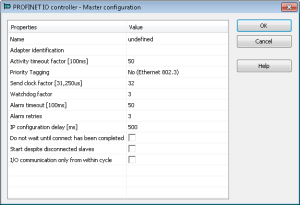
 These parameters can be changed:
Parameter
Meaning
Name
- A device name consists of labels.
- The labels must follow these conventions:
- 1 or more labels, separated by [.].
- Total length is 1 to 240.
- Label length is 1 to 63.
- Labels consist of [a...z and 0...9].
- Labels do not start or end with a hyphen [-].
- The first label does not start with port-xyz or port-xyz-abcde with a,b,c,d,e, x, y, z = 0...9.
- Device names do not have the form n.n.n.n, n = 0...999.
- Labels only start with xn- if RFC 3490 is applied.
Adapter identification
- The PROFINET adapter identification for the controllers are:
- AKD PDMM and PCMM: tsec0.
- PCMM2G: eth1.
When the application is compiled, based on the controller type, the PROFINET adapter identification is changed to match the required name.
Activity timeout factor [100ms]
- Timeout for the connection establishment to the devices.
- Maximum time between beginning of connection establishment and the first cyclic data exchange.
- Timeout factor based on 100ms.
Priority Tagging
- Yes: cyclic data exchange without priority tag.
- No: data exchange with priority tag.
Send clock factor [31,250µs]
- Send the clock factor.
- Multiple of 31,250µs (32 = 1ms).
Watchdog factor
Watchdog factor (default 3):
- The watchdog factor defines how many frames may be missing until the device is set back. Watchdog triggers:
- a) frames may be lost (e.g., due to bad cabling).
- b) frames may arrive delayed due to blocking situations in the network (e.g., due to a non-separated network).
- The watchdog may be triggered as soon as earlier file transfer occurs between the controller and the IDE when the default value is used.
- Increase this value if you encounter frequent watchdog triggers.
Alarm timeout [100ms]
Alarm timeout (default 50).
Alarm retries
Number of alarm retries (default 3).
IP configuration delay [ms]
- IP configuration delay (default 500).
- Defines the time to wait whether some devices are not ready after start.
Do not wait until connect has been competed
- Click the Do not wait until connect has been competed checkbox to start the application immediately.
- Clear the Do not wait until connect has been competed checkbox to start the application after all devices are connected.
Start despite disconnected slaves
- Click the Start despite disconnected slaves checkbox to start the application despite configured but not found devices.
- Clear the Start despite disconnected slaves checkbox to start the application if all configured devices were found only.
I/O communication only from within cycle
- Click the I/O communication only from within cycle checkbox to run IO communication from within the VM-cycle.
- Clear the I/O communication only from within cycle checkbox to run IO communication outside the VM-cycle.
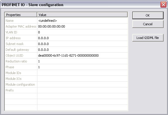
- Mark the controller and click Insert > Insert Slave/Datablock to add a PROFINET IO device.
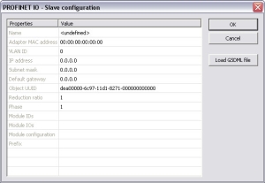 These parameters can be changed:
Parameter
Meaning
Name
- A device name consists of labels.
- The labels must follow these conventions:
- 1 or more labels, separated by [.].
- Total length is 1 to 240.
- Label length is 1 to 63.
- Labels consist of [a...z and 0...9].
- Labels do not start or end with a hyphen [-].
- The first label does not start with port-xyz or port-xyz-abcde with a,b,c,d,e, x, y, z = 0...9.
- Device names do not have the form n.n.n.n, n = 0...999.
- Labels only start with xn- if RFC 3490 is applied.
Adapter MAC address
MAC address of the PROFINET IO device.
VLAN ID
Virtual LAN ID.
IP address
IP address of the device.
Subnet mask
Subnet mask for the IP address of the device.
Default gateway
Default gateway.
Object UUID
UUID of the device.
Reduction ratio
Reduction ratio (default 16):
- The Reduction ratio defines the frequency for data to be exchanged with the device.
- The transfer rate is calculated by <Send clock factor> * 31,250 µs * <Reduction ratio>.
- The Send clock factor is a master parameter with a default value of 32.
- All known devices work with this Send clock factor.
- All known devices work with this Send clock factor.
- Example:
- With the default setting of:
- 16, the data transfer rate is 48ms.
- 2, the data transfer rate is 2ms.
- With the default setting of:
- Most devices support Reduction ratio settings of 1, 2, 4, 8, 16, 32, etc.
Phase
Phase
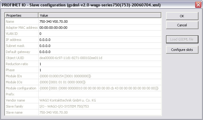
Module IDs
Module IDs of the device modules.
Module IOs
Module IOs of the device modules.
Module configuration
Module configuration.
Prefix
Prefix for the variables.
With the calculation of <Watchdog factor> x <Reduction ratio> x <Send clock factor> x 31,250µs, you get the time that may expire between two frames until the device is set back.
Example: For the default settings 3 * 32 * 31,250µs the connection is set back after 3ms of missing frames.
For office networks this time is rather low.
It is recommended to us a Reduction ratio of 32 and a Watchdog factor of 24 for such networks.
Example: The connection is reset after 24 x 32 x 32 x 31,250µs = 768ms.
If this data exchange rate is to low, separate the PROFINET IO network from the office network (e.g., by a router).
- Click Load GSDML file to import the necessary GSDML file.
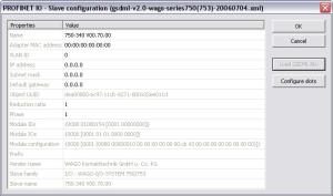
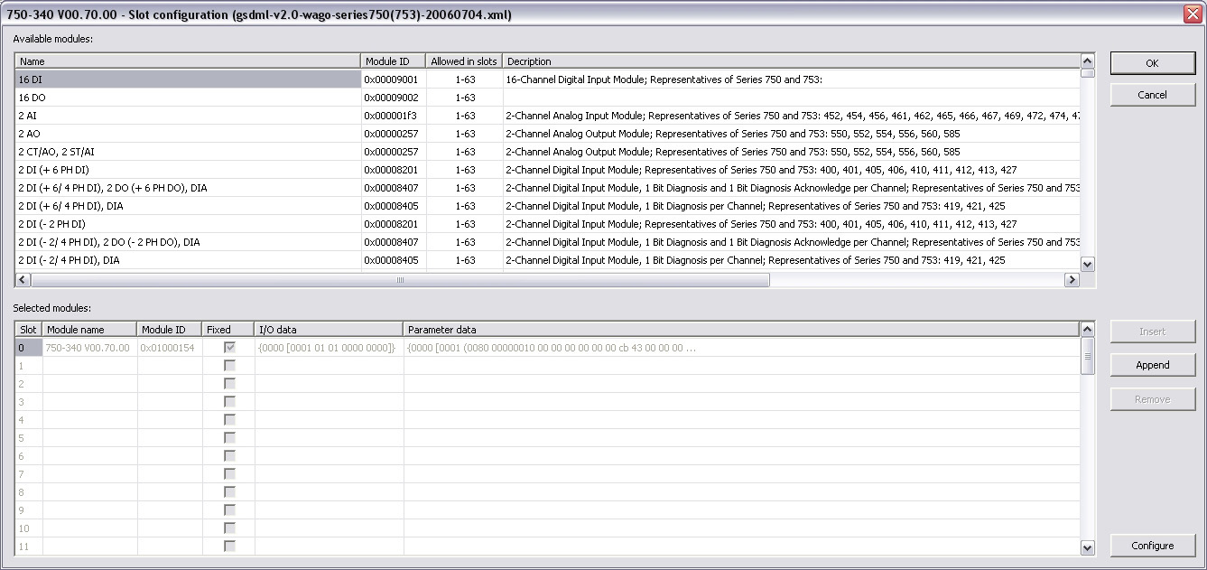
- Do the slot configuration after the GSDML file import.
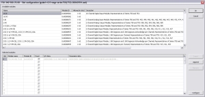
- Select the modules in the upper list.
With the buttons Insert and Append the modules are copied to the lower list.You can not configure each module.
Only modules with some sub modules respectively with a sub module with parameter data can be configured.
Mark the according module in the lower list and click the Configure button.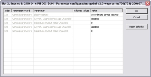
Figure 1: Example of configuring sub-modules.
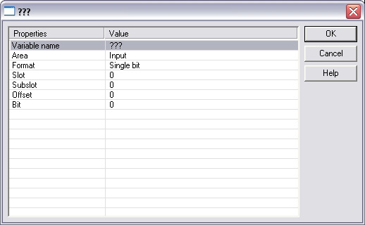
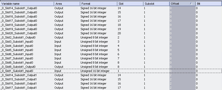
- Connect the variables with the I/Os.
Use Insert > Insert/Set Variable to append a variable to a device.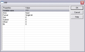 These parameters can be changed:
Parameter
Description
Variable name
Variable name following the IEC 61131-3 syntax.
Area
- Output, Output IOCS, Output IOPS.
- Input, Input IOCS, Input IOPS.
- Device status or PNIO status.
Format
- 32-bit float
- Signed:
- 8-bit integer
- 16-bit integer
- 32-bit integer
- Single bit
- Unsigned:
- 8-bit integer
- 16-bit integer
- 32-bit integer
Slot
Slot Number.
Subslot
Subslot Number.
Offset
Offset
Bit
Bit
The offset of a variable is relative to a sub module.
Thus also depending from a slot and subslot.
The offset of the first variable of a sub module is always 0 (zero).
- All settings can be changed in the grid too.
The information refers to the items of the selected item in the configuration tree.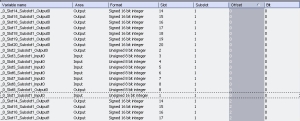
If the GUI Views is online with a target system, the table shows the real-time data of the variables.