Configure a PROFINET IO Device
The Runtime manages a mapping table containing the PROFINET IO Inputs and Outputs.
The KAS-IDE contains a fully integrated configurator for a PROFINET IO RT controller or device.
The PROFINET maximum data size is 1440 bytes Input length and 1440 bytes Output length.
To calculate the size, use the slot configuration view to count the number of bits per slot and convert to bytes.
Example: 7 slots containing 16 outputs of 32-bits each, is 7 x 16 x 32 = 3584 bits = 448 bytes.
-
-
Referring to the PROFINET standard, the units of a PROFINET network are named as IO Controllers (Masters) and IO Devices (Slaves).
-
-
PROFINET is only supported on AKD PDMM, PCMM, and PCMM2G controllers.
Configuration Procedure
- Open the fieldbus configuration window.
- Right-click in the window and select Insert > Insert Network.
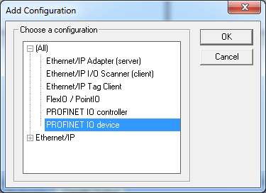
The Add Configuration dialog opens.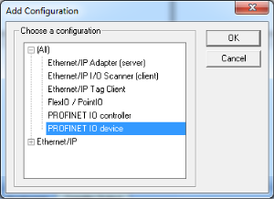
- Select PROFINET IO device and click OK.
The configuration is represented as a tree:
- Profinet IO Configuration
- Profinet IO device (*)
- Group (*)
- Variable (*)
- Group (*)
(*) These items can appear several times in the configuration (depending on the bus topology).
- Profinet IO device (*)
The I/Os of the PROFINET network must be connected to the variables via a PROFINET IO device.
- Profinet IO Configuration
- Right-click the PROFINET IO device network and click Insert Master/Port.
This starts the declaration of a PROFINET device.
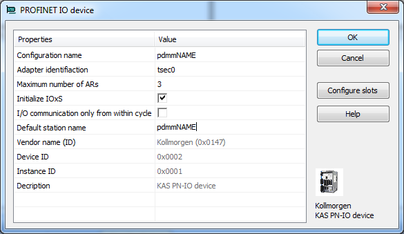
The PROFINET IO device dialog opens: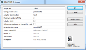
 These parameters can be changed:
Parameter
Meaning
Configuration Name
- A device name consists of labels.
- The labels must follow these conventions:
- 1 or more labels, separated by [.].
- Total length is 1 to 240.
- Label length is 1 to 63.
- Labels consist of [a...z and 0...9].
- Labels do not start or end with a hyphen [-].
- The first label does not start with port-xyz or port-xyz-abcde with a,b,c,d,e, x, y, z = 0...9.
- Device names do not have the form n.n.n.n, n = 0...999.
- Labels only start with xn- if RFC 3490 is applied.
Adapter identification
- The PROFINET adapter identification for the controllers are:
- AKD PDMM and PCMM: tsec0.
- PCMM2G: eth1.
When the application is compiled, based on the controller type, the PROFINET adapter identification is changed to match the required name.
Maximum number of ARs
Maximum number of alarm retries (default 3).
Initialize IOxS
- Click the Initialize IOxS checkbox to initialize IOxS with good status.
- Clear the Initialize IOxS checkbox to stop initialization of IOxS.
I/O communication only from within cycle
- Click the I/O communication only from within cycle checkbox to run IO communication from within the VM-cycle.
- Clear the I/O communication only from within cycle checkbox to run IO communication outside the VM-cycle.
Default station name
Name of the station.
- Click OK to save the changes or selections and close the dialog.
- Click the Configure Slots button.
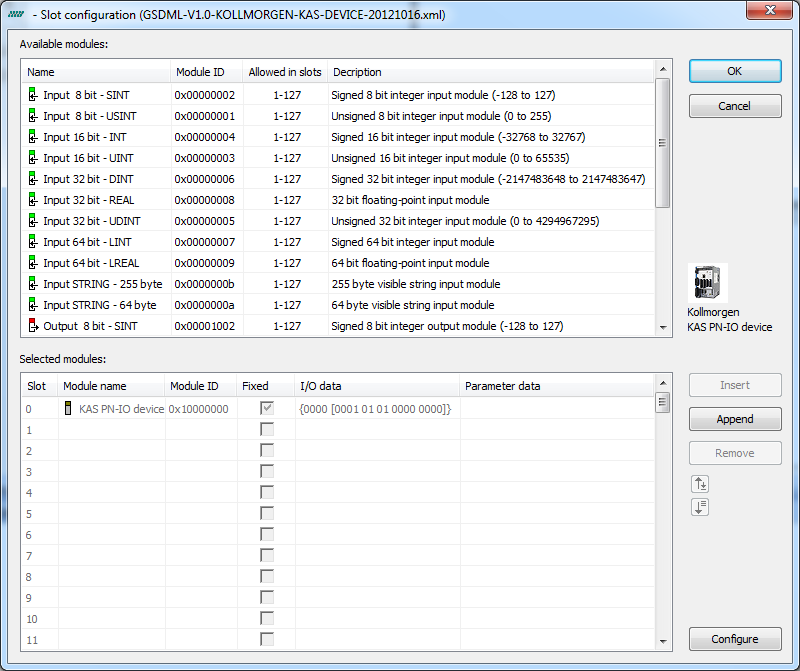
The Slot Configuration dialog opens.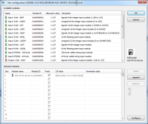
- Select the modules in the upper list.
With the buttons Insert and Append the modules are copied to the lower list.You can not configure each module.
Only modules with some sub modules respectively with a sub module with parameter data can be configured.
Mark the according module in the lower list and click the Configure button. - Click OK to close the Slot Configuration dialog.
- Click OK to close the device window.
- Click the Insert Variables button.
- Right click on the master and select Create Variables.
This automatically populates the variables and groups.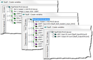
Every PROFINET variable is expanded to a set of Boolean variables in PLC by default.
Example: A SINT slot is mapped to eight PLC BOOL variables.
If you have many configured slots, many PLC variables are produced.
The controller is slowed by a large amount of PLC variables.To avoid this, you can right click on a slot in the Create variables dialog and select Pack bits.
Example: With a SINT slot, this creates one SINT variable in KAS instead of eight BOOL variables.
This helps reduce the number of PLC variables and reduces the load on the controller.
The Pack bits action may be applied to all slots by right clicking on the root node in the Create variables dialog.
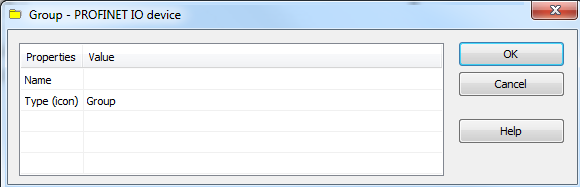
- Right-click the device and select Insert Slave to add a group.
 These parameters can be changed:
Parameter
Meaning
Name
Name of the group
Type (icon)
Icon used for the group
- Now you can connect the variables with the I/Os.
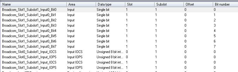
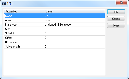
Right-click the group and choose Insert Symbol to append a variable to a device. These parameters can be changed:
Parameter
Description
Variable name
Variable name following the IEC 61131-3 syntax.
Area
- Output, Output IOCS, Output IOPS.
- Input, Input IOCS, Input IOPS.
- Device status or PNIO status.
Format
- 32-bit float
- Signed:
- 8-bit integer
- 16-bit integer
- 32-bit integer
- Single bit
- Unsigned:
- 8-bit integer
- 16-bit integer
- 32-bit integer
Slot
Slot Number.
Subslot
Subslot Number.
Offset
Offset
Bit
Bit
The offset of a variable is relative to a sub module.
Thus also depending from a slot and subslot.
The offset of the first variable of a sub module is always 0 (zero).

- All settings can be changed in the table.
- The information refers to the items below of the selected item in the configuration tree.
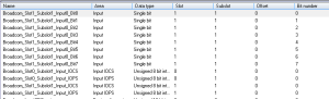
- If KAS is connected to a target system and the system is running, the table shows the real-time data of the variables.