![]()
 Function Block - Performs a slave axis move which follows the master axis based on the ratio specified by RatioNumerator and RatioDenominator.
Inputs
|
Input |
Data Type |
Range |
Unit |
Default |
Description |
|---|---|---|---|---|---|
|
Execute |
BOOL |
FALSE, TRUE |
N/A |
No default |
On the rising edge, request to queue the slave gear ratio move. |
|
Master |
AXIS_REF |
1 to 256 |
N/A |
No default |
Name of a declared instance of the AXIS_REF library function.
|
|
Slave |
AXIS_REF |
1 to 256 |
N/A |
No default |
AXIS_REF.AXIS_NUM is the slave axis number. See AXIS_REF Structure. |
|
RatioNumerator |
DINT |
-2147483648 to 2147483647 |
N/A |
No default |
Numerator of master/slave ratio. The + or - sign indicates the direction for the slave axis. |
|
RatioDenominator |
DINT |
-2147483648 to 2147483647 |
N/A |
No default |
Denominator of master/slave ratio.
|
|
MasterSyncPosition |
LREAL |
-1.7E308 to 1.7E308 |
N/A |
No default |
Master axis sync position. 14 to 15 significant digits of accuracy. |
|
SlaveSyncPosition |
LREAL |
-1.7E308 to 1.7E308 |
N/A |
No default |
Slave axis sync position. 14 to 15 significant digits of accuracy. |
|
SyncMode |
INT |
0 to 1 |
N/A |
No default |
SyncMode determines the allowed conditions for synchronization.
|
|
MasterStartDistance |
LREAL |
-1.7E308 to 1.7E308 |
User units |
No default |
When the master axis reaches this distance before MasterSyncPosition, the slave axis begins its lock-on process.
|
|
BufferMode |
SINT |
1 |
N/A |
No default |
|
Outputs
|
Output |
Data Type |
Range |
Unit |
Description |
|---|---|---|---|---|
|
StartSync |
BOOL |
FALSE, TRUE |
N/A |
Indicates the master axis has reached the MasterStartDistance from the MasterSyncPosition and the lock-on process has begun. |
|
InSync |
BOOL |
FALSE, TRUE |
N/A |
Indicated the slave axis is locked on to the master axis. |
|
Busy |
BOOL |
FALSE, TRUE |
N/A |
High from the moment the Execute input goes high until the time the move is ended. |
|
Active |
BOOL |
FALSE, TRUE |
N/A |
Indicates this move is the Active move. |
|
CommandAborted |
BOOL |
FALSE, TRUE |
N/A |
Indicates the move was aborted. If the abort arises because the inputs cause inconsistent motion, then this FB:
|
|
Error |
BOOL |
FALSE, TRUE |
N/A |
Indicates either:
|
|
ErrorID |
INT |
No range |
N/A |
Indicates the error if the Error output is set to TRUE. |
Remarks
SlaveCommandPosition = MasterActualPosition * RatioNumerator / RatioDenominator
-
- This function block starts a motion-related action and stores data for calculations and error checking.
If using a dual-core controller, see Call Function Blocks Multiple Times in the Same Cycle.
- See Function Blocks - General Rules about how inputs and outputs work.
- This function block allows the application to specify sync positions for the master and slave axes.
- It is the point in which the master and slave axes become engaged in synchronous motion.
- When the master axis reaches the MasterStartDistance from the MasterSyncPosition, the slave axis begins to accelerate to the target velocity determined by the master axis velocity and the ratio.
- The slave axis arrives at the target velocity and the SlaveSyncPosition at the same time the master axis arrives at the MasterSyncPosition.
- At that time, the slave is locked on to the master and follows the master at the ratio specified.
- The slave axis continues to follow the master axis until this move is aborted.
Aborting Gearing
Gearing functions can generate large accelerations while following the master.
- If the aborting function block has small, non-zero Jerk, or small acceleration values, it can take a long time for an accelerating axis to reach the target velocity, or position of the aborting function block.
- If the Jerk and/or acceleration of the aborting function cannot be increased to suitable values, it may be desirable to either:
- Abort the gearing function with an MC_GearOut with higher accelerations and/or Jerk values (or zero jerk value).
- Execute the next MC motion function block (e.g., MC_Halt).
- If the Jerk and/or acceleration of the aborting function cannot be increased to suitable values, it may be desirable to either:
Time to Reach the Target Velocity
While following the master, gearing functions can generate large accelerations.
- If the gearing function is aborted while the axis is currently accelerating, and the aborting function block has small non-zero Jerk or small acceleration values, it can take a long time to reach the target velocity, or position of the aborting function block.
- If the Jerk and/or acceleration of the aborting function cannot be increased to suitable values, it may be desirable to either:
- Abort the gearing function with an MC_GearOut with higher accelerations and/or Jerk values (or zero jerk value).
- Execute the next MC motion function block (e.g., MC_Halt).
- If the Jerk and/or acceleration of the aborting function cannot be increased to suitable values, it may be desirable to either:
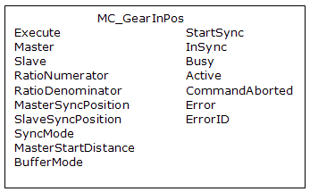
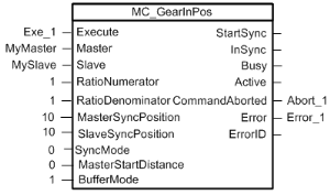
Figure 1: MC_GearInPos
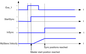
Time Diagram
Figure 2: Time Diagram
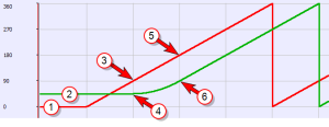
Example
- Master and Slave are rotary axes with rollovers at 360 degrees.
- The Master initial position is 0 degrees and the slave initial position is 45 degrees.
- The GearInPos FB commands the slave to accelerate up to the geared ratio (1:1) during the master start distance (90 degrees) and be synchronized with the master at the master and slave sync positions.
|
FBD Language Example
Not available.
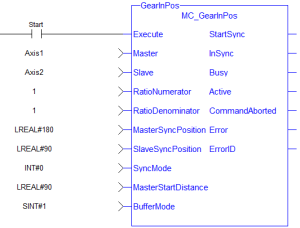
FFLD Language Example
IL Language Example
Not available.
ST Language Example
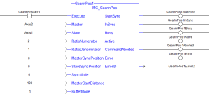
            (* MC_GearInPos ST example *)

Inst_MC_GearInPos( GearInPosReq, Axis1, Axis2, 2, 1, 0, 0, 0, 100.0, 1 );
//Inst_MC_GearInPos is instance of MC_GearInPos
GearInPosSync:= Inst_MC_GearInPos.InSync;
//store InSync output into user defined variable
