Modular EtherCAT Concept
Introduction
A modular approach to machine design has many benefits, including flexibility, scalability, and improved efficiency.
- Modular machines are split into sub-sections.
- Each sub-section containing all the mechanical and electrical devices, motors, sensors, etc. as well as corresponding application code, to work together to provide a functional segment in the manufacturing workflow.
- The advantages to modular design are realized when the modules can be re-used.
- Examples include multiple module instances in the same machine and modules replicated across multiple machines.
Special consideration should be given to the physical layout, EtherCAT network topology, and the application code architecture to design a modular machine.
Modular machines are well suited to distributed EtherCAT device topologies (e.g., AKD-x-C/N drives) but can also be applied to other EtherCAT devices.
Examples of Modular Machine Design Uses
Machine with Multiple Variants
- Machine Variant = Base module + one, two, (or more) additional modules.
- Base Module - Each machine variant has the same base set of EtherCAT devices.
- Additional Modules - Each module contains one (or more) EtherCAT devices.
Module Maintenance
- One (or more) modules are removed during machine operation.
- The machine continues to operate with the remaining base + modules.
Share Modules across Machines in a Factory Line
- Remove a module from machine A.
- Continue to operate machine A with the remaining base + modules.
- Move the module to machine B.
Modular Design Guidelines
These sections provide guidelines for modular design:
- Start with the full topology of EtherCAT devices planned for the maximum machine configuration.
- Perform an EtherCAT scan to discover the full set of EtherCAT devices and save the project file.
The PLC code in the KAS project can be adapted to handle the cases where modules containing EtherCAT devices are disconnected and removed for different machine configurations, maintenance, etc.
Map the axes to the drives for the maximum EtherCAT topology.
The axis to drive map remains consistent if drives are disconnected/removed.
Whether drives are disconnected and removed from the end or from the middle of an EtherCAT network, the axis to drive map relationship remain the same.
The PLC application code must be adapt to the disconnected/removed devices.
Because disconnected drives behave as simulated axes/drives, the application code can perform many normal axis operations without code adaptations.
This provides flexibility for how the application code is designed to handle disconnected/removed drives.
FSoE Masters may not support modular EtherCAT designs.
If a safety device is disconnected and removed, the FSoE master does not allow normal machine operation.
See ECATDeviceAction about how to add the ability to connect/disconnect an EtherCAT device to the program.
Backing up Modular EtherCAT Devices
This procedure should be followed to backup EtherCAT devices when the modular EtherCAT feature is used to remove devices to create a machine variant.
See Modular EtherCAT Concept for more information.
- Run the KAS application which sets up the correct EtherCAT topology for the machine variant.
- Stop the KAS application.
- Do not power cycle or reboot the controller between Steps 2 and 3.
- Backup the EtherCAT devices.
See Backup Procedure for more information.
Limitations
- The device topology order cannot be rearranged.
- The Modular EtherCAT features are not supported with imported ENI files.
The feedback position becomes zero if the device providing the Feedback Position for the Digitizing axis is removed using the ECATDeviceAction function block.
The feedback position data coming from the device is automatically connected to the digitizing axis when the device is reconnected to the EtherCAT network.
The Restore function only supports conditions where the network topology exactly matches the topology of the EtherCAT devices backup.
- There are a number of possible permutations and combinations when the Modular EtherCAT feature is used to create a machine with multiple variants.
- If a machine has a base EtherCAT module and a varying number of optional EtherCAT modules, then it is recommended that multiple backups are created:
- A base EtherCAT module backup and an optional EtherCAT module backup.
Example
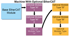
This image shows a base EtherCAT module and a varying number of optional type A modules and type B modules.
We recommend that EtherCAT Devices backups be made with the following configurations in order to meet different scenarios.
- Backup #1: Base EtherCAT Module + one of Optional Module Type A.
- Backup #2: Base EtherCAT Module + one of Optional Module Type B.
With the two EtherCAT Devices backups, you may be able to restore various combinations by removing the other Optional Modules, keeping only the module you need to restore.


