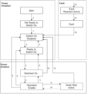
CANopen Status Machine
The states of the status machine are revealed by using the CANopen Status Word.
Figure 1: CANopen Status Machine
The start state is a pseudo-state indicating the start when the state machine is activated during the start-up sequence of the device drive's application software.
Status Description
|
Status |
Description |
|---|---|
|
Fault |
|
|
Fault reaction active |
|
|
Not ready to switch on |
The drive is not ready to switch on.
|
|
Operation enabled |
The drive is enabled and the setpoints are transferred from the EtherCAT interface.
|
|
Quick stop active |
|
|
Ready to switch on |
The drive can be enabled via the control word.
|
|
Switch on disabled |
The drive cannot be enabled via the EtherCAT interface. Example: There is no connection to a power source. |
|
Switched on |
The drive is enabled but the setpoints are not yet transferred from the EtherCAT interface.
|
Transitions of the Status Machine
The drive device supports these transitions and actions.
- The event initiates the transition.
- The transition is terminated after the action has been performed.
Transition Events and Actions
|
Transition |
Event |
Action |
|---|---|---|
|
0 |
Automatic transition after power-on or reset application. |
Drive device self-test and/or self initialization has to be performed. |
|
1 |
Automatic transition |
Communication has to be activated. |
|
2 |
Shutdown command from control device or local signal. |
None |
|
3 |
Switch on command received from control device or local signal. |
The high-level power has to be switched ON, if possible. |
|
4 |
Enable operation command received from control device or local signal. |
|
|
5 |
Disable operation command received from control device or local signal. |
The drive function has to be disabled. |
|
6 |
Shutdown command received from control device or local signal. |
The high-level power has to be switched OFF, if possible. |
|
7 |
Quick stop or disable voltage command from control device or local signal. |
None |
|
8 |
Shutdown command from control device or local signal. |
|
|
9 |
Disable voltage command from control device or local signal. |
|
|
10 |
Disable voltage or quick stop command from control device or local signal. |
The high-level power has to be switched OFF, if possible. |
|
11 |
Quick stop command from control device or local signal. |
The quick stop function has to be started. |
|
12 |
Either:
|
|
|
13 |
Fault signal |
The configured fault reaction function has to be executed. |
|
14 |
Automatic transition |
|
|
Fault reset command from control device or local signal. |
A reset of the fault condition is performed if no fault exists currently on the drive device. After leaving the Fault state, the Fault reset bit in the control word has to be cleared by the control device. |
|
|
16 |
If the quick stop option code is 5, 6, 7, or 8, enable operation command from control device |
The drive function has to be enabled. |


