Map I/O from the Project Explorer
-
- See the PDO Selection/Mapping tab about mapping I/O with third-party devices.
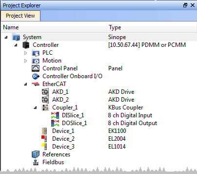
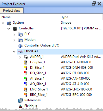
- In the Project Explorer, expand the Controller node and the EtherCAT nodes to access the devices.
- Accessing the device properties is slightly different depending upon the device.
See Access to Device Properties. - There are several ways to map variables:
- Drag and drop a variable from the Dictionary onto a table entry.
- Use the PLC Variable Creation Wizard for Kollmorgen devices.
- Directly map/unmap the Inputs/Outputs to PLC variables using the PLC Variable Selector.
-
- The Unmap command in the contextual menu is used to remove the link between the variable and the associated channels.
In addition, deleting a variable from the dictionary which is mapped to the channels also removes the links. The list of variables is filtered to display only those with relevant types.
- PLC Variable Selector displays Read Only variables when mapping the Input channels from the I/O tab.
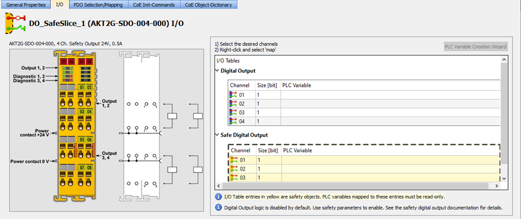
- Variables assigned to the Safe Digital Input and Safe Digital Output channels must be Read Only.
|
|
|
|
Figure 1: AKT (K-Bus) devices |
Figure 2: AKT2G (E-Bus) devices |
Select the channel(s) to map. Selection may be done by click-dragging or shift-clicking a range of entries. The entire table may be selected by clicking on its border.
After the selection is made, right-click and select Map or press <Enter>.
This opens the PLC Variable Selector.
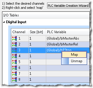
Figure 3: Map or Unmap options
Choose the variable to be linked to the channels or PDO object.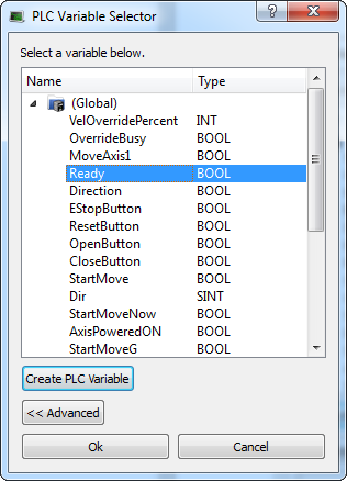
Figure 4: PLC Variable Selector dialog
-
-
The limitations of PLC variable mapping are:
- Each PLC variable can be mapped to an EtherCAT I/O and exclusively to either:
- A Controller Onboard I/O.
- An external driver.
- Because a variable can only be mapped to one channel or PDO object, when you link a variable to a new channel or PDO object, the previous mapping is removed (even if linked to another slice or device).
- Individual bits within a variable can be mapped to multiple I/O channels on different devices (AKD, AKD PDMM, PCMM, PCMM2G, or Slice).
Example: The same PLC variable cannot be mapped to both PROFINET and a Controller Onboard I/O but it is possible with a regular EtherCAT I/O.
- Each PLC variable can be mapped to an EtherCAT I/O and exclusively to either:
When a device is removed using ECATDeviceAction:
- Variable mapped to an Analog or Digital Input Type
- The value of the variable becomes '0' when the mapped device is removed.
- The device I/O value is automatically reconnected to the variable when the device is reconnected to the network.
- Variable mapped to an Analog or Digital Output
- The value is not sent to the device when the mapped device is removed.
- When the device is reconnected, the value is sent to the I/O automatically.
All of the I/Os mapped to the X22 connector are grayed out in the IO tab:
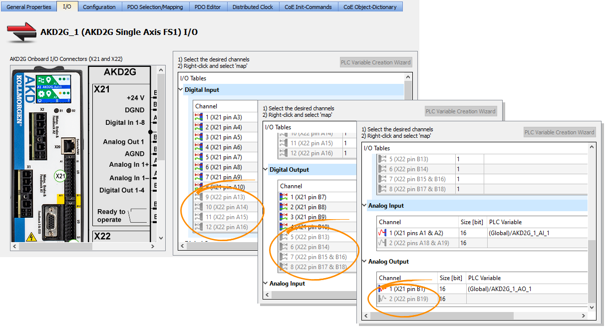
Figure 5: X22 I/O Map
-
-
AKD2G drives are available with various I/O options.
An AKD2G drive of one variant can be replaced in the KAS project with a drive that has a different I/O option.
See the AKD2G Model Nomenclature section in Automation and Motion Control Programmable Automation Solutions for available models and I/O options.
Access to Device Properties
|
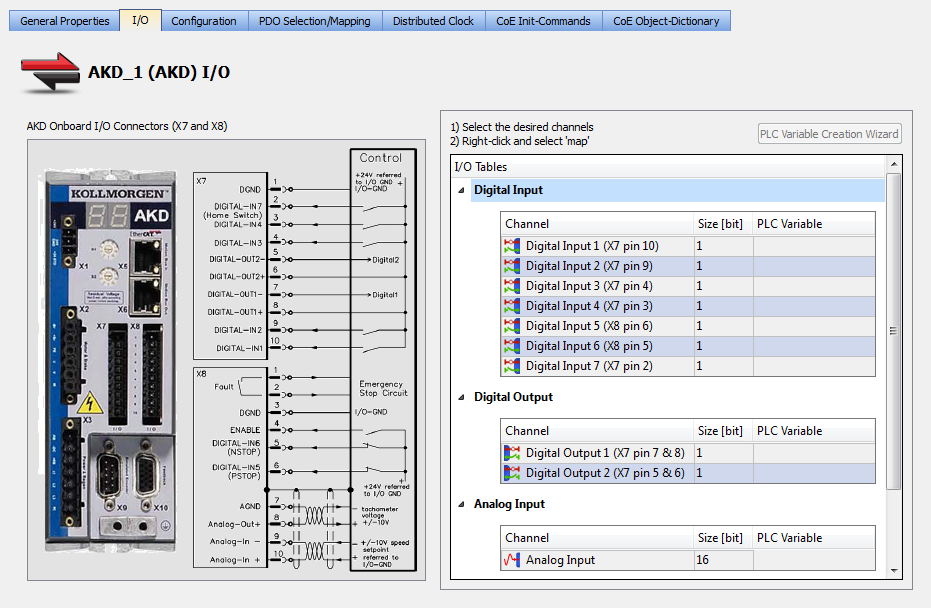
AKD or AKD2G In the project tree, double-click the drive and select the I/O tab. (Figure 6) |
|
|
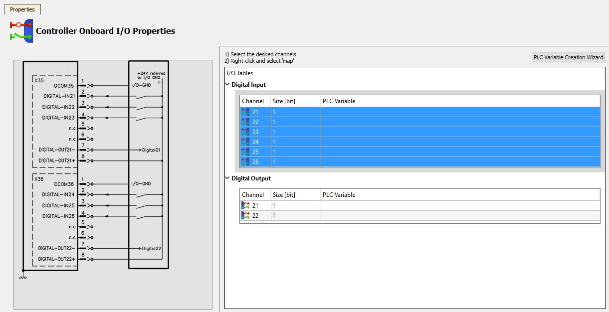
KAS Controllers In the project tree, double-click Controller Onboard I/O in the project tree. (Figure 7) |
|
|
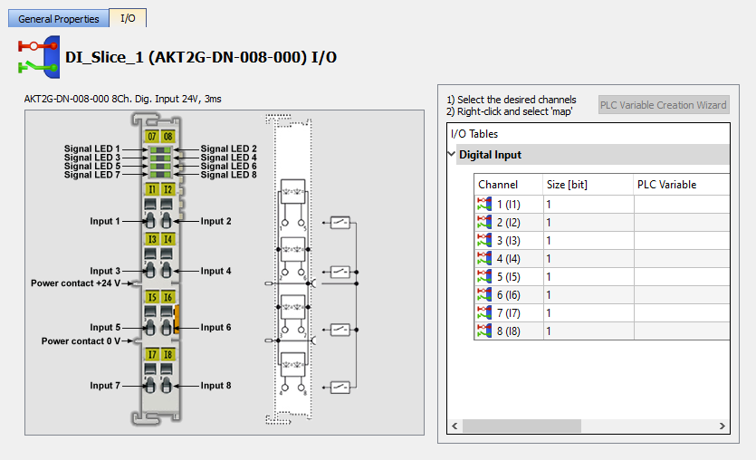
I/O Slice In the project tree, double-click the I/O Slice under EtherCAT (e.g., AKT2G) or the Coupler entry (e.g., AKT) and click the I/O tab. (Figure 8)
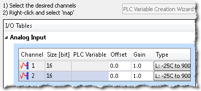
For Slice Analog I/O and thermocouples, the offset and gain parameters must be defined. (Figure 9) |
|
|
Safety I/O Slice In the project tree, double-click the Safety I/O Slice under EtherCAT (E-Bus) and click the I/O tab. (Figure 10)
|
|
See Also


