Axis Parameters
The table below is a list of Boolean parameters currently supported. These parameters are read and written by the function blocks MC_ReadBoolPar and MC_WriteBoolPar.
| Parameter | ID | Name | R/W | Update Rate Type | Description |
|---|---|---|---|---|---|
| MC_AXIS_PARAM_IN_POSITION | 1011 | Axis In-Position | Read Only | Controller | True if the axis has no active or next move queued, the command delta is 0, and the actual position is within the in-position bandwidth False otherwise, Boolean. |
| MC_AXIS_PARAM_DRIVE_WARNING | 1013 | Drive Warning | Read Only | EtherCAT Cyclic | Drive Warning Status. 1 |
| MC_AXIS_PARAM_REGIST_GOOD | 1025 | Good Registration Mark Occurred | Read Only | EtherCAT Non-Cyclic | True indicates that a good registration mark was encountered. This Boolean will be automatically reset after it has been read. 2 |
| MC_AXIS_PARAM_REGIST_BAD | 1026 | Bad Registration Mark Occurred | Read Only | EtherCAT Non-Cyclic | True indicates that a bad registration mark was encountered. This Boolean will be automatically reset after it has been read. 2 |
| MC_AXIS_PARAM_FI_OCCURRED | 1027 | Fast Input |
Read Only | EtherCAT Non-Cyclic | This parameter is deprecated. The recommended replacement is to use the "Done" output of the MC_TouchProbe function block to verify if the fast input Deprecated behavior: True if a fast input occurred on either Capture Engine 0 or Engine 1. This Boolean will automatically reset after it has been read. 3 |
| MC_AXIS_PARAM_APPLY_SUPERIMPOSED_DISTANCE | 1033 | Apply Superimposed Distance | Read / Write | Controller |
If false, MC_MoveAbsolute does not take into account any added superimposed distance due to MC_MoveSuperimp. The final reported position of the axis, which does include superimposed distance, may not be equal to the Position input to MC_MoveAbsolute. Param 1033 = False If true, MC_MoveAbsolute compensates for all added superimposed distance from MC_MoveSuperimp calls at the time of the initial MC_MoveAbsolute call. The final reported position of the axis will be equal to the Position input to MC_MoveAbsolute. If MC_MoveSuperimp is called during MC_MoveAbsolute, then the final position will include the superimposed distance. Param 1033 = True The default value for this parameter is False. |
The table below is a list of non-Boolean parameters currently supported. These parameters are read and written by the function blocks MC_ReadParam and MC_WriteParam.
| Parameter | ID | Name | R/W | Update Rate Type | Description |
|---|---|---|---|---|---|
| MC_AXIS_PARAM_CMD_POS | 1 | Command Position | Read Only | Controller |
Axis command position – includes any command deltas from superimposed axes, user units. If a set position is in process (due to homing or registration, there may be a 1 cycle delay. |
| MC_AXIS_PARAM_ACT_VEL | 10 | Actual Velocity | Read Only | EtherCAT Cyclic | Axis actual velocity, User unit/sec |
| MC_AXIS_PARAM_CMD_VEL | 11 | Command Velocity | Read Only | Controller | Axis command velocity – includes any command deltas from superimposed axes, User unit/sec |
| MC_AXIS_PARAM_PHASE_SHIFT | 1000 | Phase Shift | Read Only | Controller | The amount of phase shift applied by MC_Phasing, in slave axis' user units |
| MC_AXIS_PARAM_SUPERIMPOSED_DISTANCE | 1001 | Superimposed Distance | Read Only | Controller | The cumulative distance traveled via MC_MoveSuperimp moves, user units |
| MC_AXIS_PARAM_MASTER_OFFSET | 1002 | Master Offset | Read / Write | Controller | Write: the amount to increment the master offset for an active master/slave move, user units. Read: the amount of master offset applied, user units. |
| MC_AXIS_PARAM_SLAVE_OFFSET | 1003 | Slave Offset | Read / Write | Controller | Write: the amount to increment the slave offset for an active master/slave move, user units. Read: the amount of slave offset applied, user units. |
| MC_AXIS_PARAM_MOVE_TYPE_ACTIVE | 1004 | Active Move Type | Read Only | Controller | The active move type (see table in Move Types) |
| MC_AXIS_PARAM_MOVE_TYPE_NEXT | 1005 | Next Move Type | Read Only | Controller | The queued (next) move type (see table in Move Types) |
| MC_AXIS_PARAM_POSITION_ERROR | 1006 | Position Error | Read Only | EtherCAT Cyclic | Position error in user units |
| MC_AXIS_PARAM_FEEDBACK_LAST | 1007 | Raw Feedback | Read Only | EtherCAT Cyclic | Raw Feedback position in user units. Keeps track of the actual position based on the physical feedback device |
| MC_AXIS_PARAM_ROLLOVER_POSITION | 1008 | Rollover | Read / Write | Controller | The axis rollover position in user units. If the axis is a servo axis, this parameter can only be written when there are no moves in the queue. 1 |
| MC_AXIS_PARAM_VELCOMP_FACTOR | 1009 | Velocity Compensation Factor | Read / Write | Controller | The factor used to multiply the velocity compensation value to account for the number of updates of delay in transmission of the feedback value from the drive to the control. See Velocity Compensation for more information. 1 |
| MC_AXIS_PARAM_VELCOMP_FILTER | 1010 | Velocity Compensation Filter | Read / Write | Controller | The number of updates in which to apply a change in velocity compensation. See Velocity Compensation for more information. 1 |
| MC_AXIS_PARAM_IN_POSITION_BAND | 1012 | Axis In-Position Bandwidth |
Read / Write | Controller | The bandwidth about the command position to determine the state of the in-position flag. 2 |
| MC_AXIS_PARAM_DRIVE_STATUS | 1014 | Drive Status | Read Only | EtherCAT Cyclic |
Drive Status Word (Similar to MLAxisStatus) Some status bits are set only at program startup. |
| MC_AXIS_PARAM_UU_PER_REV | 1015 | User Units Per Rev | Read Only | Controller | User units per motor revolution (UU/FBU Ratio). See About the User Units to Feedback Units Ratio below. 1 |
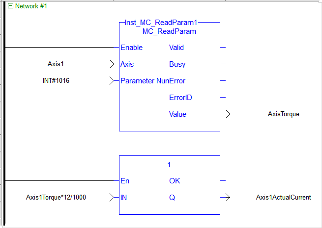
| MC_AXIS_PARAM_TORQUE_ACTUAL | 1016 | Actual Torque |
Read Only | EtherCAT Cyclic | The actual torque |
| MC_AXIS_PARAM_BUS_ADDRESS | 1017 | Drive Address | Read Only | Controller | Drive address value to be used in EtherCAT fieldbus functions as drive address. Before using in fieldbus functions, this value needs to be converted to integer by using a convert any to DINT function. 1 |
| MC_AXIS_PARAM_SENSOR_DELAY | 1018 | Sensor |
Read / Write | Controller | Compensation for Physical sensor |
| MC_AXIS_PARAM_INTERP_CMD_POS | 1019 | Interpolated Command Position | Read Only | Controller | Command position solely from this axis’s interpolator (in user units). This value does not include any command deltas from other axes that are currently superimposed upon it. |
| MC_AXIS_PARAM_INTERP_CMD_VEL | 1020 | Interpolated Command Velocity | Read Only | Controller | Command velocity solely from this axis’s interpolator (in user units). This value does not include any command deltas from other axes that are currently superimposed upon it. |
| MC_AXIS_PARAM_REGIST_COMP | 1021 | Registration Compensation | Read Only | Controller | The latest calculated registration compensation value. This value is updated each time a good registration mark is encountered. This value is in User Units. |
| MC_AXIS_PARAM_REGIST_DIST | 1022 | Distance Between the Last Two Good Registration Marks | Read Only | EtherCAT Non-Cyclic | Distance between the last two good registration marks. This value is in User Units. 2 |
| MC_AXIS_PARAM_REGIST_GOOD_CNT | 1023 | Number of Consecutive Good Registration Marks | Read / Write | EtherCAT Non-Cyclic | Number of consecutive good registration marks. This value is incremented each time a good registration mark is encountered and automatically zeroed when a bad registration mark is encountered. The ability to write this parameter is provided to allow the application to zero this value. 2 |
| MC_AXIS_PARAM_REGIST_BAD_CNT | 1024 | Number of Consecutive Bad Registration Marks | Read / Write | EtherCAT Non-Cyclic | Number of consecutive bad registration marks. This value is incremented each time a bad registration mark is encountered and automatically zeroed when a good registration mark is encountered. The ability to write this parameter is provided to allow the application to zero this value. 2 |
| MC_AXIS_PARAM_FBK_PER_REV | 1028 | Feedback Units Per Rev | Read Only | Controller | Feedback units per motor revolution (UU/FBU Ratio). See About the User Units to Feedback Units Ratio below. |
| MC_AXIS_PARAM_CM_ACT_CMD_POS | 1029 | Coordinated Motion Applied Command Position | Read Only | Controller | Amount of motion actually applied to the PLCopen |
| MC_AXIS_PARAM_CM_CMD_POS | 1030 | Coordinated Motion Command Position | Read Only | Controller | Amount of motion requested of a PLCopen axis by the Coordinated Motion commands. |
| MC_AXIS_PARAM_INGEAR_BANDWIDTH | 1031 | "In Gear" bandwidth | Read/Write | Controller | The bandwidth about the target slave velocity in which the slave axis will lock onto the master axis and the "InGear" output will turn on for the MC_GearIn function block; User unit/sec (Default value 0.1 User units/sec). 1 |
| MC_AXIS_PARAM_DRIVE_AXIS_NUMBER | 1032 | Drive Axis Number | Read Only | Controller | One-based number that specifies the axis on the drive |
- This is a configuration parameter.
- There is some delay is acquiring fast input information from drives as well as calculating the registration marks. While the information is evaluated cyclically, there may be a few cycles between when the fast input occurs and the system records the registration marks.
- There is some delay is acquiring fast input information from drives as well as calculating the fast input position. While the information is evaluated cyclically, there may be a few cycles between when the fast input occurs and the system records the fast input data.
| Update Rate Type | Description |
|---|---|
| EtherCAT Cyclic | Update rate depends on the EtherCAT (link to ECAT update page EtherCAT Master Settings) and KAS application program (link to Define the PLC Cycle) update rates |
| EtherCAT Non-Cyclic | Update rate depends on the update rate of reading the parameter through Ethercat (Link to times to read non-cyclic parameters [? does the time come from ECATReadSDO FB or from the MCReadParam DriveReadParam FB EtherCAT Library]) and KAS application program update rate |
| Controller | Update rate depends on KAS application program update rate (link to Define the PLC Cycle) |
-
-
About the User Units to Feedback Units Ratio
Parameters 1015 and 1028 are set during the MC_CreatePLCAxis function block execution. These two parameters work together to form the User Units to Feedback Units Ratio (UU/FBU Ratio). The drive interface units are fixed by the drive and define the drive units per revolution, which is used to command the drive per the ratio.
Example
For an AKD drive where the drive interface units are set to 1048576 units per revolution:
- A ratio of 360 UU / 1048576 FBU will generate 360 UU per revolution of the drive motor.
- A ratio of 720 UU / 1048576 FBU will generate 720 UU per revolution of the drive motor.
- A ratio of 720 UU / 2097152 FBU will generate 360 UU per revolution of the drive motor.
- A ratio of 360 UU / 2097152 FBU will generate 180 UU per revolution of the drive motor.
As noted in MC_CreatePLCAxis, the Feedback Units per Revolution term must be a power of 2.
After reading the current via MC_ReadParam, the following equation converts current to amps for a 12 amp peak drive:
MC_AXIS_PARAM_TORQUE_ACTUAL * Drive Peak Current Rating / 1000