Function Block Diagram (FBD)
Use of ST instructions in graphic languages
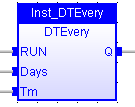
The name of the operation or function, or the type of function block is written within the block rectangle. In case of a function block call, the name of the called instance is written in the header of the block rectangle, such as in the example below:
Data flow
The data flow represents values of any data type. All connections must be from input and outputs points having the same data type.
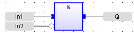
In case of a Boolean connection, you can use a connection link terminated by a small circle, that indicates a Boolean negation of the data flow. Draw FBD connection lines.
The data flow must be understood from the left to the right and from the top to the bottom. It is possible to use labels and jumps to change the default data flow execution.
FFLD symbols
FFLD symbols can also be entered in FBD diagrams and linked to FBD objects. Refer to the following sections for further information about components of the FFLD language:
Special vertical lines are available in FBD language for representing the merging of FFLD parallel lines. Such vertical lines represent a OR operation between the connected inputs. Below is an example of an OR vertical line used in a FBD diagram: