


SLA (Safely Limited Acceleration)
SLA description for drive option Functional Safety 3.
Description
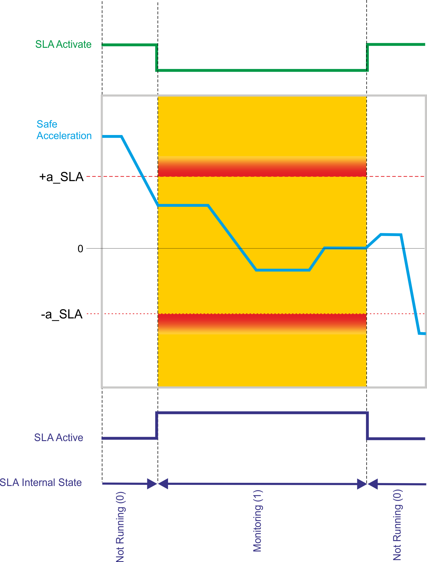
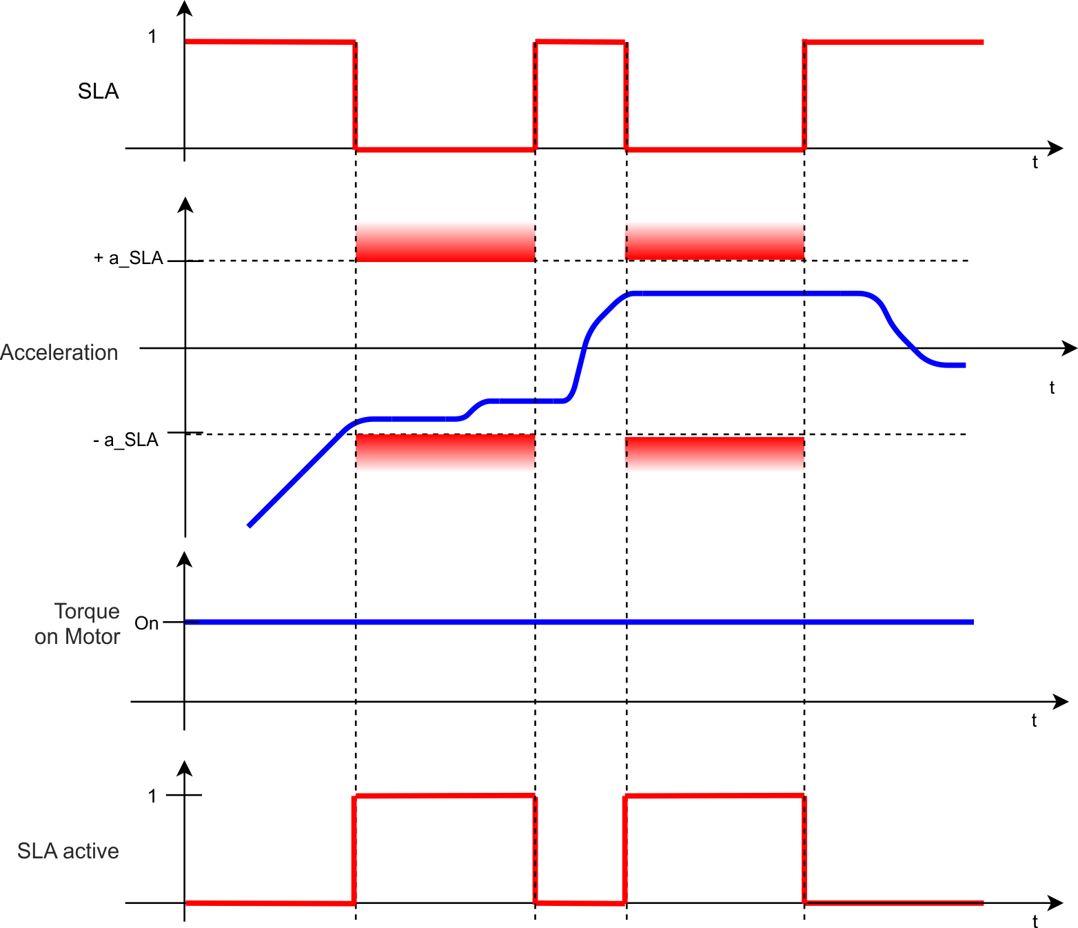
SLA, when active, monitors the acceleration and ensures that it stays in an acceleration window. The acceleration window is described by the unsigned parameter a_SLA where -a_SLA defines the lower limit and +a_SLA defines the upper limit. If the acceleration leaves the acceleration window, a configurable fault reaction will be activated.
Number of Instances
One instance per axis.
Function Input / Output Variables
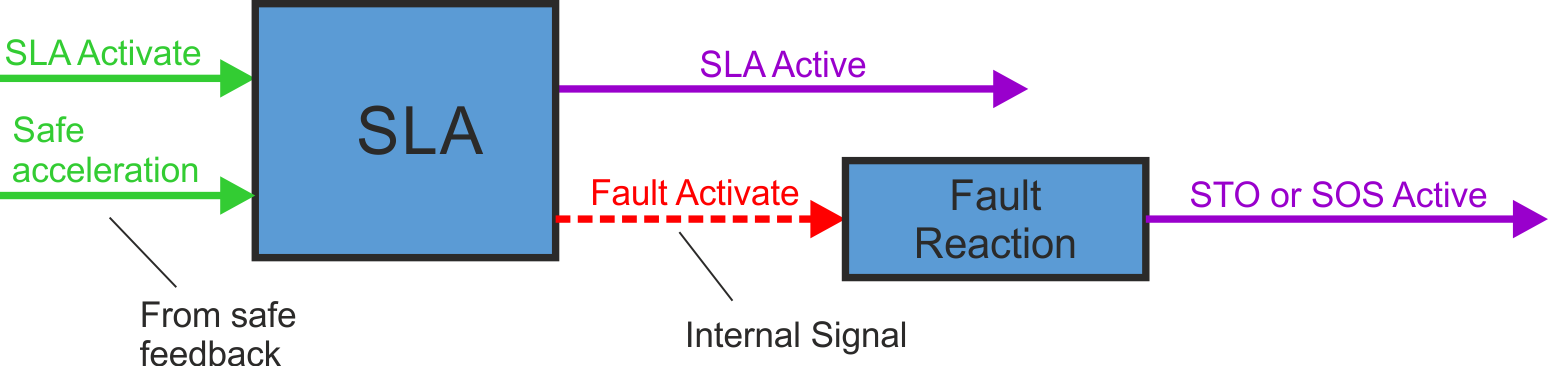
Inputs
- SLA Activate can be triggered by FSoE or safe digital inputs (must be mapped)
- Safe acceleration: signal from safe feedback
Outputs
- SLA Active: logical status of the SLA function
- Fault Activate: activate fault reaction
Activation
|
Activation by FSoE |
|
|
Activation by safe digital inputs |
|
Timing
Related Parameters
Safety parameters
|
Name |
Variables |
Default |
Parameter |
|---|---|---|---|
|
Function Activation |
- |
0 (Never active) |
|
|
Safe Input |
- |
0 (Not used) |
|
|
FSoE |
- |
0 (Not used) |
|
|
Acceleration Limit |
a_SLA |
1 (Acc user units) |
|
|
Fault Reaction |
- |
1 (STO) |
Diagnostic parameters
| Name |
Variables |
Default |
Parameter |
|---|---|---|---|
|
Function Active Status |
- |
- |
|
|
Function Internal Status |
- |
- |
State Diagram
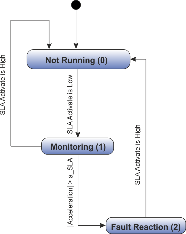
SLA is active if internal state is "Monitoring (1)" or "Fault reaction (2)".
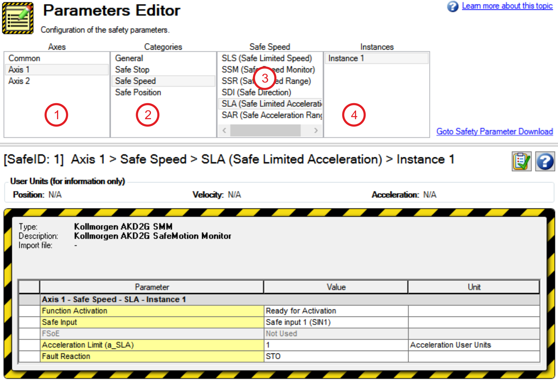
Setup in WorkBench
Select the drive and open the Safety Parameterization view (see "Parameters Editor").
Choose the axis (1), category (2) and the SLA function (3).
Fault Reaction / Failure Messages
SLA has a configurable fault reaction. STO is used by default but can be replaced by SS1 Instance 1 or SS2 Instance 1. When the fault reaction is activated, SLA remains active and the internal state (AXIS#.SAFE.SLA.INTERNALSTATE) is set to failed state (2).
Safety State / Status Signals
The signal AXIS#.SAFE.SLA.ACTIVE can be monitored by safe digital outputs with OSSD pulses (see "OSSD"). The status signal must be mapped to the safe digital output. Two outputs can be combined to a dual channel output. For parameter description refer to Functional Safety Parameter Reference.
Safety Properties
Refer to Safety Properties Overview.


