AKT2G-AN-240-000
2-channel input terminal PT100 (RTD) for resistance sensors, 16 bit, 2-, 3-wire system.
Jump to a section on this page:
The AKT2G-AN-240 analog input terminal allows resistance sensors to be connected directly. The AN-240 circuitry can operate 2- and 3-wire sensors. Several characteristic sensor curves (Pt100, Pt1000, NI120, NI1000, KTY types and others) are supported.
The terminals from the AKT2G-AN-240 can measure the temperature at the measuring point or directly output the resistance values of the sensors. For temperature measurements the temperature value is calculated via the characteristic curves stored in the terminal.
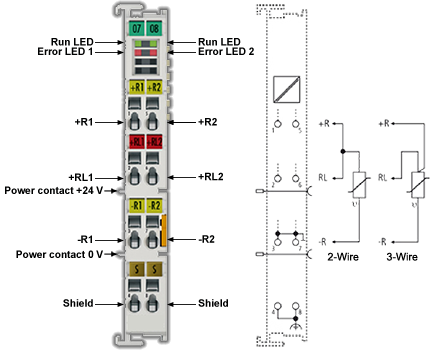
The EtherCAT Terminals indicate their signal state by means of light emitting diodes. Sensor malfunctions such as broken wires are indicated by error LEDs.
See also: Notices on Analog Specifications for information on
- Measuring Error / Measurement Deviation
- Temperature Coefficient tK [ppm/K]
- Single-Ended / Differential Typification
- Common-mode voltage and reference ground (based on differential inputs)
- Dielectric strength
- Temporal Aspects of Analog/Digital Conversion
Related Topics: Map Input and Output to Variables
Technology RTD Measuring
Function
The AKT2G-AN-240 analog input terminals allow resistance sensors in the range 0 - 4096 Ohm to be connected directly.
Functions:
- Resistance measurement
- Measuring range 0 to 1024 Ω: Resolution 1/64 Ohm
- Measuring range 0 to 4096 Ω: Resolution 1/16 Ohm
- The use of the terminal in the range from 0 to 10 Ohm is not recommended due to the relatively low measuring accuracy.
- With the AN-240 the external bridge must be inserted between +R and +RL in 3-wire mode
- Temperature measurement
The measured sensor resistance is converted directly into a temperature by the internal µC via the desired linearization characteristic curve
- Standard resolution 1/10 °C (1 digit = 0.1 °C) according to a theoretically representable temperature range [- 3276.7 to 3276.8 °C]
The physically specified temperature range for the respective sensor is to be observed!
- Various PTC sensor characteristic curves are implemented over their complete measuring range for selection in the AN-240 series: Pt/Ni xxxx, KTY xx
- Scaling and presentation can be changed
- Standard resolution 1/10 °C (1 digit = 0.1 °C) according to a theoretically representable temperature range [- 3276.7 to 3276.8 °C]
Additional notes:
- The resistance is determined by means of Ratiometric Voltage Measurement.
- The error state "broken wire" is detected as overrange, signaled as an error to the controller and indicated by the ERROR LED.
- The error state "short-circuit" is detected as underrange if the resistance is smaller than the smallest resistance of the measuring range, signaled as an error to the controller and indicated by the ERROR LED.
- In the delivery state, the measured value is displayed in increments of 1/10° C in two's complement format (integer).
- Other methods of display, e.g., high resolution with 1/100 °C can be selected via CoE 0x80n0:02.
When using the high resolution a temperature range of -320 to +320 °C (-32566 to 32567) is measurable by the 2-byte PDO.
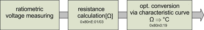
Figure 1: Display of the measurement and calculation of the resistance/temperature
Ratiometric Voltage Measurement
The AKT2G-AN-240 measures resistance ratiometrically by means of voltage comparison, see Figure 2: "3-wire connection technology":
- A constant voltage of 2.5 V is applied across a highly precise known reference resistance Rref and the sensor Rt connected in series.
- 5 kOhm reference resistor
- The sensor resistance can be determined by comparing the two voltages, V1 at reference and V2 at the sensor
- The measuring current through the sensor thus depends on the sensor resistance; this must be considered in questions of sensor self-heating
Example: at 0°C and thus 1000 Ohm internal resistance, a Pt1000 thus causes a measuring current of 0.1 mA on an AN-240.
-
-
Wiring of the input channels
Due to this measurement principle (resistive temperature sensor), a sensor may not be connected in parallel to two or more input channels!
Connection Techniques
The electrical connection of a resistance sensor to the AKT2G-AN-240 can take place using the 2-wire, or 3-wire. Since the measuring method is a resistance measurement, the sensor supply cables with their internal resistance can falsify the measurement. The following are available for this:
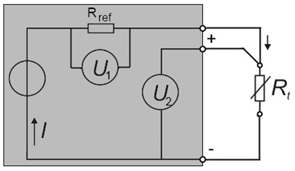
Figure 2: 3-wire connection technology
- 3-wire sensors: this simplified connection reduces wiring costs and compensates cable resistances to a considerable degree.
- 2-wire sensors: very simple connection, recommended only for short supply cables
The supply line resistances can be eliminated from the calculation in 2-wire mode if they are made known to the AN-240 in the CoE object 0x80n0:1B (unit [1/32 Ω]). The determination of the supply line resistance is possible on the application side either by measurement or by comparison.
-
-
Two-wire connection
If the AN-240 is operated with a two-wire connection, the inputs +R and +RL must be bridged by the user.
Example of line compensation in the 2-wire mode
Example of line compensation in the 2-wire mode. The cross-sectional area of the 50 meter long copper wire connecting cable is 0.5 mm2. The specific resistance of copper is 0.0175 Ω mm2 m-1.
Determination of the total resistance of the feed cable:

For a resistance change of the Pt100 of ≈0.39 Ω/K, the resulting temperature deviation is:

if the line resistance is not taken into account. If the 3.5 Ohm are now entered as

in 0x8000:1B (see "80n0:1B") this is subtracted from the measured value and the temperature is corrected accordingly.
Overview of Suitable Resistance Sensors
The following resistance sensors are suitable for temperature measurement with the AKT2G-AN-240 and can be selected via the object 0x80n0:19.
|
Type |
Resistance range |
Implemented temperature range |
|---|---|---|
|
Pt100 (0.00385 Ω/Ω/°C, IEC60751 characteristic curve Pt385) |
~ 18 ... ~390 Ohm |
-200°C to 850°C |
|
Ni100 |
|
-60°C to 250°C |
|
Pt1000 (0.00385 Ω/Ω/°C, IEC60751 characteristic curve Pt385) |
~180 ... ~3900 Ohm |
-200°C to 850°C |
|
Pt500 |
|
-200°C to 850°C |
|
Pt200 |
|
-200°C to 1370°C |
|
Ni1000 |
|
-60°C to 250°C |
|
Ni1000 TK5000 100°C: 1500 ohm |
|
-30 to 160°C |
|
Ni120 |
|
-60°C to 320°C |
|
KT100/110/130/210/230 KTY10/11/13/16/19 |
~500 ... ~2200 Ohm |
-55 ...150°C |
|
KTY81/82-110,120,150 |
||
|
KTY81-121 |
||
|
KTY81-122 |
||
|
KTY81-151 |
||
|
KTY81-152 |
||
|
KTY81/82-210,220,250 |
||
|
KTY81-221 |
||
|
KTY81-222 |
||
|
KTY81-251 |
||
|
KTY81-252 |
||
|
KTY83-110,120,150 |
~500 ... ~2500 Ohm |
-50...175°C |
|
KTY83-121 |
||
|
KTY83-122 |
||
|
KTY83-151 |
||
|
KTY83-152 |
||
|
KTY84-130,150 |
~350 ... ~2500 Ohm |
-40...300°C |
|
KTY84-151 |
||
|
KTY21/23-6 |
~500 ... ~4000 Ohm |
-50...150°C |
|
KTY1x-5 |
||
|
KTY1x-7 |
||
|
KTY21/23-5 |
||
|
KTY21/23-7 |
Basic Principles of RTD Technology
Certain materials change their electrical resistance if the temperature of the material changes. Thanks to this property they can be used as sensors for the measurement of temperature. Such an RTD element (Resistance Temperature Device) or thermistor then exhibits a well-known material-dependent property, i.e. how the resistance changes in relation to the temperature – the so-called characteristic. In an initial approximation this characteristic can be taken to be a linear equation:

The factor k can be positive or negative and must be specified by the sensor manufacturer:
- positive coefficient (PTC): resistance increases with increasing temperature, i.e. it conducts less well; the sensor is then referred to as a PTC thermistor
- negative coefficient (NTC): resistance increases with decreasing temperature, i.e. it conducts better; the sensor is then referred to as an NTC thermistor
The larger the coefficient, the higher the sensitivity of the sensor.
-
-
Temperature measurement
This kind of temperature measurement is to be distinguished from that using thermocouple sensors:
these spontaneously generate a (small) voltage across the conductor, which is measured at the contact points.
Within a very small measuring range nearly all materials can be described by such a linear characteristic.
However, it is often necessary to measure over a large measuring range, e.g., several tens or hundreds of °K. Within such ranges the characteristic must be described for many materials by non-linear equations of a higher order or by using exponential components. Examples of such equations are
- Platinum/PT sensors (PTC thermistor) according to IEC 60751:
- for the range -200.. 0 °C:

- for the range 0°C..850°C:

- for the range -200.. 0 °C:
The coefficients A, B and C are to be specified by the sensor manufacturer or taken from the standard. The parameter R0 indicates the resistance in ohm of the platinum sensor at T = 0 °C. The sensor designations are based on these characteristics, e.g., for PT100 R0 = 100 Ω at T=0 °C.
- Steinhart-Hart (for NTC thermistor)

The coefficients a, b, c should be specified by the sensor manufacturer, or they can be determined by measuring the resistance at three known temperatures.
- B-parameter equation (for NTC thermistor)

The coefficients RT0, B, T0 should be:
- specified by the sensor manufacturer or
- be determined by measuring the resistance at two known temperatures.
The B-parameter equation is a simplified version of the Steinhart-Hart equation.
- The B-parameter itself is only constant in a small range, e.g., between 25 °C.. 50 °C or 25 °C.. 85 °C, which is identified as: B25/50 or B25/85.
- The accuracy of the equation strongly depends on the B-parameter.
- The larger the measuring range, the lower the accuracy. If a larger measuring range required, it is preferable to use the Steinhart-Hart equation.
- and others
A typical characteristic is shown for each of the NTC and PTC families in following figure:
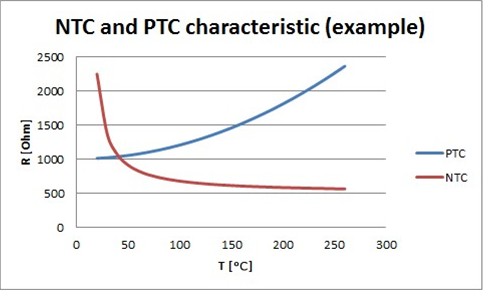
Figure 3: Examples for temperature-dependent resistance values
Hence, there is no such thing as a general NTC or PTC sensor – in fact, they are names for sensor families with a certain behavior.
For common sensors / characteristics such as PT100, these characteristics are already permanently implemented into the measuring devices. The user must check whether a sensor that he intends to use is supported by the measuring device. The following criteria apply here:
- Temperature range: does the sensor support the intended temperature range?
- Measuring range: can the sensor resistance be measured in the intended temperature range?
- Characteristic curve: can the measured resistance be converted accordingly into temperature? (base point, gradient/coefficient)
- Velocity: how often is the resistance measured?
In a quite basic way, a sensor manufacturer can of course also publish the characteristic of its sensor as a value table.
-
-
Resistance measurement
To determine the resistance it is usual to pass a measuring current in the mA range (< 5 mA) through the sensor and to measure the resulting voltage. Three effects must be taken into consideration when doing this:
- the measuring current can lead to self-heating of the sensor. However, this usually has only a minimal effect on the measuring accuracy.
Special sensors tend to be used for cryogenic applications.
- the sensor supply lines also always have a resistance and add a (usually) constant additional resistance to the measurement. This can be compensated by
- 3-wire connection of the sensor
- manually accounting for the known wire resistance in the calculation
- using a sensor with a higher nominal resistance – the supply line effects are then of less consequence
- Insulation faults or thermovoltages can affect the measurement.
For classification there follows an overview of the NTC/PTC properties of various sensors:
|
NTC |
PTC |
|---|---|
|
many semiconductors |
many metals |
|
various ceramics |
various ceramics |
|
NTC20, NTC100, etc. |
Pt100, Pt1000, .. |
|
|
KTY .. |
|
|
Ni100, Ni1000, .. |
|
|
FeT |
-
-
Sensor exchange
Please note that 1:1 exchangeability is not always guaranteed, especially in the case of manufacturer-specified sensors. If necessary, the new sensor must be re-calibrated in the system.
LEDs and Connection
-
-
Two-Wore Connection
If the AKT2G-AN-240 is operated with a two-wire connection, the inputs +R and +RL must be bridged by the user.
|
LED |
Color |
Meaning |
|
|---|---|---|---|
|
RUN |
green |
This LED indicates the terminal's operating state: |
|
|
off |
State of the EtherCAT state machine: INIT = initialization of the terminal or BOOTSTRAP = function for firmware updates of the terminal |
||
|
flashing |
State of the EtherCAT state machine: PREOP = function for mailbox communication and different standard-settings set |
||
|
Single flash |
State of the EtherCAT state machine: SAFEOP = verification of the sync manager channels and the distributed clocks. Outputs remain in safe state |
||
|
on |
State of the EtherCAT state machine: OP = normal operating state; mailbox and process data communication is possible |
||
|
ERROR1, ERROR2 |
red |
Short circuit or wire breakage. The resistance is in the invalid range of the characteristic curve |
|
|
Terminal point |
No. |
Comment |
|---|---|---|
|
+R1 |
1 |
Input +R1 |
|
+RL1 |
2 |
Input +RL1 |
|
-R1 |
3 |
Input -R1 |
|
Shield |
4 |
Shield (internally connected to terminal point 8) |
|
+R2 |
5 |
Input +R2 |
|
+RL2 |
6 |
Input +RL2 |
|
-R2 |
7 |
Input -R2 |
|
Shield |
8 |
Shield (internally connected to terminal point 4) |
Connection of Analog RTD Signal Lines
The RTD input terminals of the AN-240 measure the analog resistance of the sensor. The voltage drop at the sensor (including the line resistances, depending on the connection technology) is equivalent to the sensor resistance and therefore a measure for the sensor temperature, if the characteristic sensor curve is known. The following procedure serves for connecting analog signal cables in order to ensure error-free measurement of the analog signals.
Measures
- Sensor cable to be used:
- Tightly twisted
- Shielded copper braid
- Use low-impedance cable, particularly for 2-wire connection.
- Keep the sensor and sensor cables free from external potential.
On no account should the GND connections (3/7) be connected with other potentials.
- The resistor for the RTD sensor (e.g., 100 or 1000 Ω nominal) should be chosen based on the ratio between sensor resistance and line resistance, taking account of the connection type (2/3-wire).
Shielding Measures
-
-
Shielding Measures
Due to the complexity in the "EMC" area, there is no generally applicable guideline, but only technical measures in accordance with the state of the art, which can sometimes contradict each other. These must be checked for feasibility and effectiveness, taking into account the plant specifications, and applied by the plant installer following assessment.
The following notes on shielding are to be understood as technical suggestions that have proven themselves from time to time in practical use. It must be checked in each case which measures can be applied, depending on the installation and plant. The effectiveness of each measure must be checked individually. The formal transferability of measures to other types of plant is in general not possible.
Priority is to be given to typical national or general normative specifications.
A shielding approach is described below that in many cases improves the measurement quality. The suggested measures must be checked for feasibility and effectiveness in the actual plant.
- Apply the shield with a low resistance and enveloping the cable by 360°
- at the entry point into the control cabinet, the shield should be earthed conductively
- the shield should be earthed again at the terminal
- at the terminal connection point, if present
- if no terminal connection point is available, earth the shield as close to the terminal as possible.
- to avoid ground loops the shield can be undone after entry into the control cabinet. A capacitive connection to the terminal shield contact is possible.
- avoid unshielded cable lengths of > 50 cm!
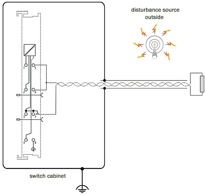
|
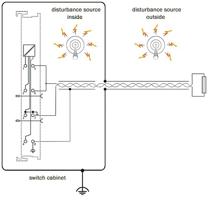
|
| In the case of potential interference sources inside the control cabinet | In the case of potential interference sources inside and outside the control cabinet |
Settings and Application Notes for AN-240
Default Setting
The AKT2G-AN-240 can be used for direct temperature or resistance measurements. The corresponding CoE settings are shown in the following table.
The relationship between temperature and resistance of a Pt100/Pt1000 sensor is shown below:
|
Temperature |
typical resistance, approx. |
|---|---|
|
850°C |
Pt1000: 3.9 kΩ Pt100: 390 Ω |
|
320°C |
Pt1000: 2.2 kΩ Pt100: 220 Ω |
|
-200°C |
Pt1000: 180 Ω Pt100: 18 Ω |
Characteristic sensor curves are available from the sensor manufacturers.
| AKT2G-AN-240 | |
|---|---|
|
Default/factory setting |
|
|
Area of application |
The terminal is calibrated in the measuring range “1/16 Ω” (10 Ω to 4 kΩ) and can be used in this resistance range. |
Notice regarding Resistance Measurement mode
In Resistance Measurement mode the measured value is always displayed unsigned, irrespective of the Presentation setting (object 0x80n0:02), as 0..xFFFF with the respective value.
1/16 Ω -> ~62 mΩ/Digit
1/64 Ω -> ~15 mΩ/Digit
Basics About Signal Isolators, Barriers
Occasionally, analog signals cannot be fed directly from the sensor to the analog input module, in which case a special intermediary device must be added.
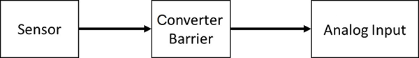
Reasons may include:
- The sensor may be installed in hazardous locations and protected according to the intrinsic safety ignition protection type (Ex i) while a module is not yet available for the desired application
- Separate electrical isolation between the sensor and the module is required
- The sensor has an electrical output signal for which does not yet offer a suitable input module.
The type of intermediate device depends on this criteria:
- Electrical signal supplied by the sensor: voltage 10V or µV, AC or DC, 20mA or 1A, resistance
- the sensor must be powered in some way, e.g.
- an IEPE sensor requires 2..8 mA constant current
- a resistor requires a measuring current
- an electronic sensor may need a 24V supply, or it may be fed via a 20 mA loop
- What dynamic transmission quality for AC signals must the sensor provide via the intermediate device? Each intermediate device influences the analog signal, e.g., in terms of frequency-dependent attenuation, crosstalk, line resistance or bandwidth. This must be taken into account when an intermediate device is used in a metrological application.
- Is the device used for energy limitation in accordance with the intrinsic safety ignition protection type (Ex i)? In this case, a barrier with appropriate approval is required. Zener barriers are often used in such situations. They are made up of resistors, fuses and Zener diodes.
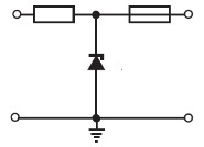
As already mentioned, these can influence the analog signal quality with respect to the above features, e.g., by temperature-dependent change of the internal resistance. Terms: Zener barrier
- Does it have to ensure electrical isolation of the analog signal?
Does electrical isolation of the analog signal have to be provided? Devices that electrically isolate the transmitted signal reconfigure the signal, so that in this case special attention must be paid to the signal influence. In this case the analog properties of the isolator and the analog module are interlinked. The properties of the isolator are dominant, particularly when ELM measurement modules or other high-quality analog modules are used. On the output side, they typically supply standard signals, such as 10 V or 20 mA. Compared with the use of external devices for electrical isolation, the use of Kollmorgen input modules with channel-based electrical isolation is advantageous. Terms: signal isolator, signal converter, signal transducer, isolating amplifier, measuring amplifier, level transducer
- Are both measures, i.e. explosion protection according to ignition protection type Ex i and electrical isolation necessary? In this case, so-called isolation barriers are used, which ensure energy limitation for intrinsic safety and also electrical isolation of the signal. See the notes on analog signal influence.
From a metrological point of view, signal-influencing intermediate devices should be avoided if possible.
Technical Data
|
Technical Data |
AKT2G-AN-240-000 |
|---|---|
| Approval | CE ATEX cULus |
| Connection method | 2-, 3-wire (Preset: 3-wire) |
| Conversion time | approx. 800ms - 2ms (configurable), depending on configuration and filter setting approx. 85ms, preset |
| Current consumption from the Ebus | Typ. 190mA |
| Dimensions (W x H x D) | approx. 15 mm x 100 mm x 70 mm (connected width: 12 mm) |
| Electrical isolation | 500 V (E-bus/field voltage) |
| EMC immunity/emission | conforms to EN 61000-6-2 / EN 61000-6-4 |
| Installation | on 35 mm mounting rail according to EN 60715 |
| Installation position | variable |
| Measuring current (depending on the sensor element and temperature) | typ. < 0.5 mA |
| Measuring error | for Pt sensors: < ±0.5 °C at ambient temperature 0°C ... +55°C < ±1.5 °C in the extended temperature range |
| Number of inputs | 2 |
| Permissible ambient temperature range during operation | -25℃ to +60℃ (extended temperature range) |
| Permissible ambient temperature range during storage | -40°C ... +85°C |
| Permissible relative humidity | 95%, no condensation |
| Power supply for electronics | via the E-Bus |
| Protection class | IP20 |
| Resolution (default) | 0.1°C per digit |
| Sensor types | Pt100, Pt200, Pt500, Pt1000, Ni100, Ni120, Ni1000 KT/KTY from firmware 06 Resistance measurement 10 Ω to 1 kΩ or 10 Ω to 4 kΩ (e.g., for potentiometer connection). |
| Temperature range | Range-dependent: -200…+850°C (Pt sensors); -60…+250°C (Ni sensors) |
| Vibration / shock resistance | conforms to EN 60068-2-6 / EN 60068-2-27, see also Mounting and Wiring of I/O Terminals. |
| Weight | approx. 60 g |
| Width in the process image | max. 8-byte input |