AKT2G-AN-400-000
4-channel thermocouple input terminal, preset to type K, with wire breakage detection, 16 bit
Jump to a section on this page:
See Notices on Analog Specifications for information on:
- Measuring Error / Measurement Deviation
- Temperature Coefficient tK [ppm/K]
- Common-mode voltage and reference ground (based on differential inputs)
- Dielectric strength
- Temporal Aspects of Analog/Digital Conversion
Related Topics: Map Input and Output to Variables
Thermocouple Technology Basics
The thermocouple terminals can evaluate thermocouples of the types B, C, E, J, K, L, N, R, S, T, and U. The characteristic curves are linearized and the reference temperature determined directly within the terminal.
Temperatures are output in 1/10 °C (device-dependent). The terminal is fully configurable via the Bus Coupler or the control system. Different output formats may be selected or own scaling activated. In addition, linearization of the characteristic curve and determination and calculation of the reference temperature (temperature at the terminal connection contacts) can be switched off.
Measuring principle of the thermocouple
Thermocouples can be classified as active transducers. They exploit the thermo-electric effect (Seebeck, Peltier, Thomson). A voltage referred to as thermovoltage occurs over the length of a cable with different temperatures at both ends. It is an unambiguous function of the temperature and the material. In a “TC element” this effect is utilized by operating two different conductor materials in parallel.
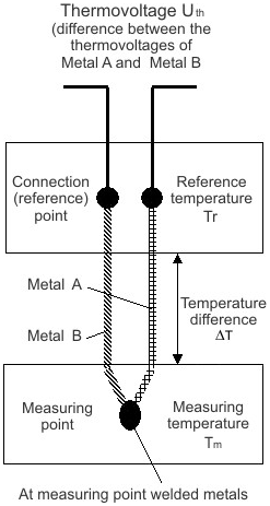
Figure 1: Principle of the Thermocouple
Example: In this example, the voltage Uth is given which is present at a type-K thermocouple at the temperature Tm.
Uth = (kNiCr - kNi) x ΔT
with
ΔT = Tm - Tv
A type-K thermocouple consists of a junction of a nickel-chrome alloy and nickel, where kNiCr and kNi represent the thermoelectric coefficients of nickel-chrome and nickel respectively. By adapting the equation according to Tm, the sought-after temperature can be calculated from the voltage measured across the thermocouple. Based on the difference to the cold junction temperature, the temperature at the measurement point can be determined to an accuracy of better than one tenth of a Kelvin with the aid of the above thermocouple equation.
-
-
Sensor Circuit
A modification of the sensor circuit with additional devices such as change over switches or multi-plexer decreases the measure accuracy. We strongly advise against such modifications.
Internal conversion of the thermovoltage and the reference voltage
Since the coefficients are determined at a reference temperature of 0 °C, it is necessary to compensate for the effect of the reference temperature. This is done by converting the reference temperature into a reference voltage that depends on the type of thermocouple, and adding this to the measured thermovoltage. The temperature is found from the resulting voltage and the corresponding characteristic curve.
Uk = Um+ Ur
Tout = f(Uk)
Overview of suitable thermocouples
These thermocouples are suitable for temperature measurement:
|
Type (according |
Element |
Implemented Temperature Range |
Color Coding (sheath - plus pole - minus pole) |
|---|---|---|---|
|
B |
Pt30%Rh-Pt6Rh |
600°C to 1800°C |
grey - grey - white |
|
C * |
W5%Re-W25%Re |
0°C to 2320°C |
n.d. |
|
E |
NiCr-CuNi |
-100°C to 1000°C |
violet - violet - white |
|
J |
Fe-CuNi |
-100°C to 1200°C |
black - black - white |
|
K |
NiCr-Ni |
-200°C to 1370°C |
green - green - white |
|
L ** |
Fe-CuNi |
0°C to 900°C |
blue - red - blue |
|
N |
NiCrSi-NiSi |
-100°C to 1300°C |
pink - pink - white |
|
R |
Pt13%Rh-Pt |
0°C to 1767°C |
orange - orange - white |
|
S |
Pt10%Rh-Pt |
0°C to 1760°C |
orange - orange - white |
|
T |
Cu-CuNi |
-200°C to 400°C |
brown - brown - white |
|
U ** |
Cu-CuNi |
0°C to 600°C |
brown - red - brown |
* not standardized according to EN60584-1
** according to DIN 43710
-
-
Maximum cable length to the thermocouple
Without additional protective measures, the maximum cable length from the EtherCAT Terminal to the thermocouple is 30 m. For longer cable lengths, suitable surge protection should be provided.
LEDs
|
LED |
Color |
Meaning |
|
|---|---|---|---|
|
RUN |
green |
This LED indicates the terminal's operating state: |
|
|
off |
State of the EtherCAT State Machine: INIT = initialization of the terminal |
||
|
flashing uniformly |
State of the EtherCAT State Machine: PREOP = function for mailbox communication and different standard-settings set |
||
|
flashing slowly |
State of the EtherCAT State Machine: SAFEOP = verification of the sync manager channels and the distributed clocks. Outputs remain in safe state |
||
|
on |
State of the EtherCAT State Machine: OP = normal operating state; mailbox and process data communication is possible |
||
|
flashing rapidly |
State of the EtherCAT State Machine: BOOTSTRAP = function for terminal firmware updates |
||
|
ERROR1-4 |
red |
Short circuit or wire breakage. The resistance is in the invalid range of the characteristic curve. |
|
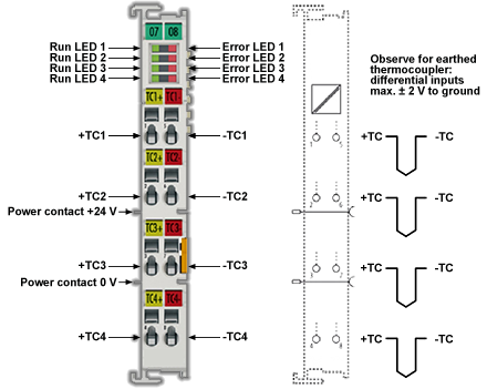
Connection Instructions for Earthed/Potential-Free Thermocouples
Due to the differential inputs of the terminals, different connection types are recommended depending on the type of thermocouple used. For earthed thermocouples, ground is not connected to the shielding. If the thermocouple does not have a ground connection, the ground and shielding contacts can be connected (see "AKT2G-AN-400-000").
-
-
Connection instructions for thermocouples
- Earthed thermocouple
- Do not connect GND to the shielding
- Potential-free / earth-free thermocouple
- GND can be connected to the shielding
- or: GND can connected to any potential, max. 35 V to 0 V power
- Non-potential-free thermocouple
- Do not connect GND to the shielding
- Do not connect GND to thermocouple potential.
- Thermocouple-potential max. 35 V to 0 V power
- Unused inputs
- Unused inputs should be short-circuited (low-resistance connection of +TC, -TC)
- Earthed thermocouple
Shielding Measures
-
-
Shielding Measures
Due to the complexity in the "EMC" area, there is no generally applicable guideline, but only technical measures in accordance with the state of the art, which can sometimes contradict each other. These must be checked for feasibility and effectiveness, taking into account the plant specifications, and applied by the plant installer following assessment.
The following notes on shielding are to be understood as technical suggestions that have proven themselves from time to time in practical use. It must be checked in each case which measures can be applied, depending on the installation and plant. The effectiveness of each measure must be checked individually. The formal transferability of measures to other types of plant is in general not possible.
Priority is to be given to typical national or general normative specifications.
A shielding approach is described below that in many cases improves the measurement quality. The suggested measures must be checked for feasibility and effectiveness in the actual plant.
- Apply the shield with a low resistance and enveloping the cable by 360°
- at the entry point into the control cabinet, the shield should be earthed conductively
- the shield should be earthed again at the terminal
- at the terminal connection point, if present
- if no terminal connection point is available, earth the shield as close to the terminal as possible.
- to avoid ground loops the shield can be undone after entry into the control cabinet. A capacitive connection to the terminal shield contact is possible.
- avoid unshielded cable lengths of > 50 cm!
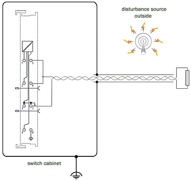
|
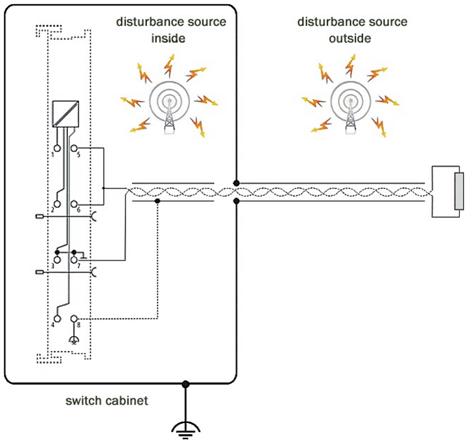
|
| In the case of potential interference sources inside the control cabinet | In the case of potential interference sources inside and outside the control cabinet |
Data Processing - TC Temperature
Settings
Presentation
index 0x80n0:02
In the delivery state, the measured value is output in increments of 1/10° C in two's complement format (signed integer).
Index 0x80n0:02 offers the possibility to change the method of representation of the measured value.
|
Measured value |
Output (hexadecimal) |
Output (signed integer, decimal) |
|---|---|---|
|
-200.0 °C |
0nF830 |
-2000 |
|
-100.0 °C |
0nFC18 |
-1000 |
|
-0.1 °C |
0nFFFF |
-1 |
|
0.0 °C |
0n0000 |
0 |
|
0.1 °C |
0n0001 |
1 |
|
100.0 °C |
0n03E8 |
1000 |
|
200.0 °C |
0n07D0 |
2000 |
|
500.0 °C |
0x1388 |
5000 |
|
850.0 °C |
0x2134 |
8500 |
|
1000.0 °C |
0x2170 |
10000 |
- Signed Integer:
The measured value is presented in two’s complement format.
Maximum presentation range for 16 bit = -32768 .. +32767Example:
- 1000 0000 0000 0000bin = 0x8000hex = - 32768dec
- 1111 1111 1111 1110bin = 0nFFFEhex = - 2dec
- 1111 1111 1111 1111bin = 0nFFFFhex = - 1dec
- 0000 0000 0000 0001bin = 0n0001hex = +1dec
- 0000 0000 0000 0010bin = 0n0002hex = +2dec
- 0111 1111 1111 1111bin = 0x7FFFhex = +32767dec
- Absolute value with MSB as sign:
The measured value is output in magnitude-sign format.
Maximum presentation range for 16 bit = -32767 .. +32767Example:
- 1111 1111 1111 1111bin = 0nFFFFhex = - 32767dec
- 1000 0000 0000 0010bin = 0x8002hex = - 2dec
- 1000 0000 0000 0001bin = 0x8001hex = - 1dec
- 0000 0000 0000 0001bin = 0n0001hex = +1dec
- 0000 0000 0000 0010bin = 0n0002hex = +2dec
- 0111 1111 1111 1111bin = 0x7FFFhex = +32767dec
- High resolution (1/100 C°):
The measured value is output in 1/100 °C steps.
Siemens Bits
index 0x80n0:05
If the bit in index 0x80n0:05 is set, status displays are shown for the lowest 3 bits. In the error case "overrange" or "underrange", bit 0 is set.
Underrange, Overrange
Undershoot and overshoot of the measuring range (underrange, overrange), index 0x60n0:02, 0x60n0:03
- Uk > Ukmax: Index 0x60n0:02 and index 0x60n0:07 (overrange and error bit) are set. The linearization of the characteristic curve is continued with the coefficients of the overrange limit up to the limit stop of the A/D converter or to the maximum value of 0x7FFF.
- Uk < Ukmax: Index 0x60n0:01 and index 0x60n0:07 (underrange and error bit) are set. The linearization of the characteristic curve is continued with the coefficients of the underrange limit up to the limit stop of the A/D converter or to the minimum value of 0x8000.
For overrange or underrange the red error LED is switched on.
Notch Filter (conversion times)
Notch filter, index 0x80n0:06
The AN-400 terminals are equipped with a digital filter. The filter performs a notch filter function and determines the conversion time of the terminal. It is parameterized via the indices 0x80n0:15. The higher the filter frequency, the faster the conversion time.
-
-
Index 0x80n0:06
The filter function is always active even if the bit is not set, since this is obligatory for the measurement process!
-
-
The filter characteristics are set via index 0x8000:15
The filter frequencies are set for all channels of the AN-400 terminals centrally via index 0x8000:15 (channel 1, see 80n0:15).
The corresponding indices 0x8010:15, 0x8020:15, 0x8030:15 have no parameterization function.
-
-
Conversion time
The conversion time is determined as:
No. of active channels * no. of measurements * no. of filter periods + computing time = conversion time
Example: (2 channels), 3 measurements (thermocouple, wire breakage, cold junction), filter 50 Hz
2 channels * 3 measurements * (1/50 Hz) + 6 ms ≈ 126 ms
Example: (4 channels), 3 measurements (thermocouple, wire breakage, cold junction), filter 50 Hz
4 channels * 3 measurements * (1/50 Hz) + 12 ms ≈ 252 ms
|
Filter frequency |
AKT2G-AN-400 |
|---|---|
|
5 Hz |
2.4 s |
|
10 Hz |
1.2 s |
|
50 Hz |
250 ms |
|
60 Hz |
210 ms |
|
100 Hz |
130 ms |
|
500 Hz |
33 ms |
|
1000 Hz |
24 ms |
|
2000 Hz |
20 ms |
|
3750 Hz |
19 ms |
|
7500 Hz |
19 ms |
|
15000 Hz |
19 ms |
|
30000 Hz |
19 ms |
|
mV range |
12 ms |
Limit 1 and Limit 2
Limit 1 and limit 2, index 0x80n0:13, index 0x80n0:14
A temperature range can be set that is limited by the values in the indices 0x80n0:13 and 0x80n0:14. If the limit values are overshot, the bits in indices 0x80n0:07 and 0x80n0:08 are set.
The temperature value is entered with a resolution of 0.1 °C.
Example:
Limit 1= 30 °C
Value index 0x80n0:13 = 300
Calibration
User Calibration
index 0x80n0:0A
User calibration is enabled via index 0x80n0:0A. Parameterization takes place via the indices.
- 0x80n0:17
Thermocouple offset (index 0x80nF:01, user calibration) - 0x80n0:18
Thermocouple gain (index 0x80nF:02, user calibration)
User scaling
index 0x80n0:01
The user scaling is enabled via index 0x80n0:01. Parameterization takes place via the indices.
- 0x80n0:11
User scaling offsetThe offset describes a vertical shift of the characteristic curve by a linear amount.
At a resolution of 0.1°, 1 digit(dec) corresponds to an increase in measured value by 0.1° At a resolution of 0.01°, 1 digit(dec) corresponds to an increase in measured value by 0.01
- 0x80n0:12
User scaling gainThe default value of 65536(dec) corresponds to gain = 1.
The new gain value for 2-point user calibration after offset calibration is determined as follows:
Gain_new = reference temperature / measured value x 65536(dec)
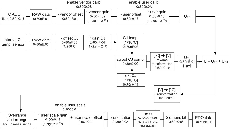
Calculation of Process Data
The concept "calibration" is used here even if it has nothing to do with the deviation statements of a calibration certificate. Actually, this is a description of the vendor or customer calibration data/adjustment data used by the device during operation in order to maintain the assured measuring accuracy.
The terminal constantly records measured values and saves the raw values from its A/D converter in the ADC raw value objects 0x80nE:01, 0x80nE:02. After each recording of the analog signal, the correction calculation takes place with the vendor and user calibration data as well as the user scaling, if these are activated (see following picture).
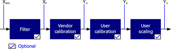
Figure 2: Calculation of Process Data
|
Calculation |
Designation |
|---|---|
|
XADC |
Output of the A/D converter |
|
XF |
Output value after the filter |
|
YH = (XADC – BH) x AH x 2-14 |
Measured value after vendor calibration, |
|
YA = (YH – BA) x AA x 2-14 |
Measured value after vendor and user calibration |
|
YS= YA x AS x 2-16 + BS |
Measured value following user scaling |
|
Name |
Designation |
Index |
|---|---|---|
|
XADC |
Output value of the A/D converter |
0x80nE:01 |
|
XF |
Output value after the filter |
- |
|
BH |
Vendor calibration offset (not changeable) |
0x80nF:01 |
|
AH |
Vendor calibration gain (not changeable) |
0x80nF:02 |
|
BA |
User calibration offset (can be activated via index 0x80n0:0A) |
0x80n0:17 |
|
AA |
User calibration gain (can be activated via index 0x80n0:0A) |
0x80n0:18 |
|
BS |
User scaling offset (can be activated via index 0x80n0:01) |
0x80n0:11 |
|
AS |
User scaling gain (can be activated via index 0x80n0:01) |
0x80n0:12 |
|
YS |
Process data for controller |
- |
-
-
Measurement Result
The accuracy of the result may be reduced if the measured value is smaller than 32767 / 4 due to one or more multiplications.
Producer Codeword
-
-
Producer Codeword
The vendor reserves the authority for the basic calibration of the terminals. The Producer codeword is therefore at present reserved.
Operation with an External Cold Junction
The AKT2G-AN-400 supports operation with an internal cold junction as standard. This means that the thermocouple is attached to the terminal points at the front of the terminal housing, so that the material transition and the cold junction are located at the front of the terminal housing. The terminal measures the cold junction temperature with its own internal temperature sensor and calculates the desired measuring point temperature value.
In special applications, operation with an external cold junction is required. The external cold junction is connected to the AN-400 with a normal copper connection cable, the material transition then takes place in the external connection point.
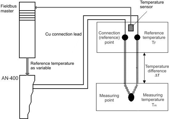
Figure 3: External cold junction
For this operation these items must be set:
- all CJCompensation PDO of the terminal must be activated, even if the "external cold junction" function is only used on isolated channels
-
In CoE 0x80n0:0C of the desired channel, the external cold junction calculation must be activated by the value "2" (external process data).
The cold junction temperature Tv must now be recorded by a separate temperature sensor at the cold junction and fed to the terminal via the fieldbus master and the fieldbus as a linked variable ("external") (see Figure 3: "External cold junction").
The separate measurement can technically be done via another thermocouple connected to an AN-400, or any other temperature measurement whose value is known to the controller.
The AN-400 then supplies the measured value Value, taking into account the temperature value supplied with CJCompensation:
The comparison data is written to CoE 0x70n0:11.
-
-
Alternative to cold junction measurement
As an alternative to the procedure described above, the cold junction can be maintained at a defined temperature through ice water (0° C), for example. In this case, the temperature is known without measurement of the cold junction temperature (Figure 3: "External cold junction") and can be reported to the AN-400 via the process data.
Interference from Equipment
When operating the AKT2G-AN-400 analog EtherCAT terminals, high frequency superimposed signals from interfering devices (e.g., proportional valves, stepper motors or DC motor output stages) can be picked up by the terminal. In order to guarantee interference-free operation, we recommend the use of separate power supply units for the terminals and the interference-causing devices.
Wire Break Detection
The AKT2G-AN-400 terminals provide a wire break detection of the connected thermocouple. A periodical testing current of several µA will be given to the thermocouple for detection. No voltage measurement takes place during test.
Due to particular cases, the testing current could have a disturbing effect, the wire break detection can be disabled by CoE (object 0x80n0:0E, "Disable wire break detection") since following firmware versions:
| AKT2G-AN-400 | |
|---|---|
| Firmware | 04 |
| ESI / Revision | 0023 |
Status Word
The status information for each channel of the AN-400 is transmitted cyclically from the terminal to the EtherCAT Master as process data (PDO). Two versions of the device description are available for the AN-400, representing the process image in individual and extended forms.
The AN-400 transmits this process data:
- Underrange: Measurement is below range
- Overrange: Range of measurement exceeded ("Cable break" together with "Error")
- Limit 1: Limit value monitoring 0: ok, 1: Limit value overshot , 2: limit range undershot
- Limit 2: Limit value monitoring 0: ok, 1: Limit value overshot , 2: limit range undershot
- Error: The error bit is set if the process data is invalid (cable break, overrange, underrange)
- TxPDO State: Validity of the data of the associated TxPDO (0 = valid, 1 = invalid).
- TxPDO Toggle: The TxPDO toggle is toggled by the slave when the data of the associated TxPDO isupdated. This allows the currently required conversion time to be derived.
The limit evaluation is set in the "8000" objects in the CoE directory.
Technical Data
|
Technical Data |
AKT2G-AN-400-000 |
|---|---|
|
Number of inputs |
4 |
|
Thermocouple sensor types |
Types J, K, L, B, E, N, R, S, T, U, C (default setting type K), mV measurement |
|
Input filter limit frequency |
1 kHz typ.; depending on sensor length, conversion time, sensor type |
|
Connection technology |
2-wire |
|
Maximum cable length to the thermocouple |
30 m |
|
Measuring range, FSV |
in the range defined in each case for the sensor (default setting: type K; -200 … +1370°C) Voltage: ± 30 mV (1 µV resolution) up to ± 75 mV (4 µV resolution) |
|
Resolution |
Internal: 16 bit Temperature representation: 0.1/0.01 °C per digit, default 0.1°C Note: 16 bit is used for FSV calculation; so, value leaps >0.01°C will occur at resolution 0.01°C depending of which thermocouple is set; e.g., type K: approx. 0.04°C |
|
Supports NoCoeStorage function |
yes, from firmware 01 |
|
Wiring fail indication |
yes |
|
Conversion time |
approx. 2.5 s to 20 ms, depending on configuration and fil ter setting, default: approx. 250 ms |
|
Measuring error |
< ±0.3 % (relative to full scale value) |
|
Voltage supply for electronics |
via the E-bus |
|
Distributed Clocks |
- |
|
Current consumption via E-bus |
typ. 200 mA |
|
Bit width in the process data image |
max. 16 byte input, max. 8 byte output |
|
Max. potential ±TC against ground |
2 V, important e.g., when operating with grounded thermocouples |
|
Max. differential voltage between the ±TC inputs |
±15 V permanent |
|
Electrical isolation |
500 V (E-bus/field voltage) |
|
Configuration |
via KAS-IDE |
|
Weight |
approx. 60 g |
|
Permissible ambient temperature range during operation |
-25°C ... +60°C (extended temperature range), from firmware 06 |
|
Permissible ambient temperature range during storage |
-40°C ... +85°C |
|
Permissible relative humidity |
95%, no condensation |
|
Dimensions (W x H x D) |
approx. 15mm x 100mm x 70mm (width aligned: 12mm) |
|
Mounting |
on 35mm mounting rail conforms to EN 60715 |
|
Vibration/shock resistance |
conforms to EN 60068-2-6 / EN 60068-2-27 See installation instructions for terminals with increased mechanical load capacity |
|
EMC immunity/emission |
conforms to EN 61000-6-2 / EN 61000-6-4 |
|
Protection class |
IP20 |
|
Installation position |
variable |
|
Approval |
CE, ATEX, cULus, IECEx |