AKT2G-ECT-000-000
EtherCAT Coupler for E-bus Terminals
Jump to a section on this page:
Overview of EtherCAT Couplers
An EtherCAT coupler is required in order to connect EtherCAT Terminals with E-bus-communication to an EtherCAT network. This coupler relays the communication from the higher level EtherCAT network to the terminals.
EtherCAT Coupler for E-bus terminals
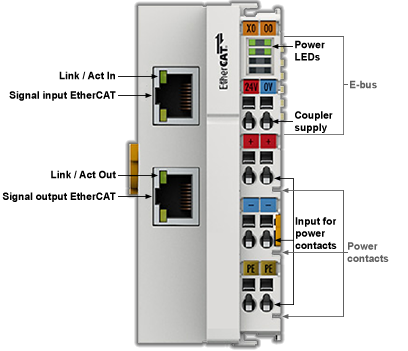
The ECT-000 coupler connects the EtherCAT Device Protocol with the EtherCAT Terminals. One station consists of a coupler, any number of EtherCAT Terminals and a bus end terminal (AKT2G-EM-000-000).
The coupler converts the telegrams from Ethernet 100BASE-TX to E-bus signal representation in passing with minimum latency. The coupler is connected to the network via the upper Ethernet interface. The lower RJ-45 socket may be used to connect further EtherCAT devices in the same strand.
The coupler supplies the connected terminals with the necessary E-bus current for communication. The coupler can supply a maximum of 5 V/2 A. Power feed terminals (AKT2G-PSF-024-000) must be integrated if more current is required.
In the EtherCAT network, the coupler can be installed anywhere, including before, after, or in the middle of the EtherCAT servo drives. However, the coupler does not support MAC Unicast or IP addressing from a switch or a router.
EtherCAT Coupler Port Allocation
According to the EtherCAT specification, an ESC (EtherCAT Slave Controller, hardware processing unit of the EtherCAT protocol) can have 1 to 4 ports, which it controls itself. Via an open port it can handle outgoing and incoming Ethernet traffic.
The following figure shows the direction of data flow in a fully connected ECT-000 as an example:
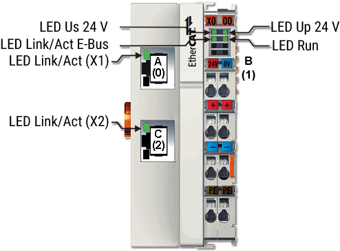
Figure 1: Example: AKT2G-ECT-000 EtherCAT coupler with 3 ports
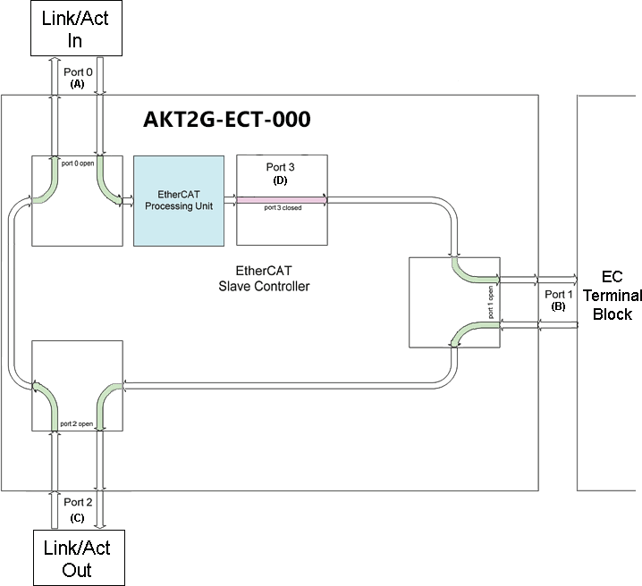
Figure 2: Internal and external port assignment for Bus Coupler AKT2G-ECT-000
Frame processing sequence
- The EtherCAT frame arriving at the EtherCAT signal input is passed on by Port 0 (A) to the EtherCAT processing unit.
- The EtherCAT frame arrives at Port 1 (B) and the data frame departs via Port 1 (B) to the following slave in the EtherCAT terminal network (if a slave is connected there and reports ‘Link’).
- After the arrival of the data frame at Port 1 (B) from the terminal network, this is passed on to Port 2 (C) and leaves the coupler at the following EtherCAT output (if a slave is connected there and reports ‘Link’).
- The data frame arrives at Port 2 (C). This is now forwarded to port 0 (A) and leaves the ECT-000 via the EtherCAT input.
-
-
Processing of the data
The data in the EtherCAT datagrams are processed only between Ports 0 (A) and 3 (D) in the EtherCAT processing unit. The non-implemented (internal) Port 3 (D) is considered to be closed and passes on the datagram to Port 1 (B).
Power Supply, Potential Groups
Bus Coupler power supply
The Bus Coupler requires a 24 VDC supply for its operation. The connection is made by means of the upper spring-loaded terminals labeled 24 V and 0 V. The supply voltage is used by the Bus Coupler electronics and for direct voltage generation for the E-bus. The voltage generation for the E-bus takes place in a DC/DC converter without electrical isolation.
The ECT-000 units supply the E-bus with max. 2,000 mA E-bus current. Power feed terminals are to be inserted if the added terminals require more current.
Input for power contacts
The bottom six connections with spring-loaded terminals can be used to feed the supply for the peripherals. The spring-loaded terminals are joined in pairs to a power contact. The feed for the power contacts has no connection to the voltage supply for the Bus Coupler. The design of the feed permits voltages of up to 24 V. The assignment in pairs and the electrical connection between feed terminal contacts allows the connection wires to be looped through to various terminal points. The current load via the power contacts may not permanently exceed 10 A; the supply line must therefore be protected by a 10 A fuse (slow-blow).
Power contacts
On the right hand face of the Bus Coupler there are three spring contacts for the power contact connections. The spring contacts are hidden in slots so that they can not be accidentally touched. By attaching a Bus Terminal the blade contacts on the left hand side of the Bus Terminal are connected to the spring contacts. The tongue and groove guides on the top and bottom of the Bus Coupler and of the Bus Terminals guarantees that the power contacts mate securely.
The current load of the power contacts may not permanently exceed 10 A.
Electrical isolation
The bus couplers operate by means of three independent potential groups. The supply voltage feeds the E- bus electronics in the bus coupler and the E-bus itself, which are electrically isolated. The supply voltage is also used to generate the operating voltage for the fieldbus.
-
-
All the Bus Terminals are electrically isolated from the E-bus. The E-bus is thus electrically isolated from everything else.
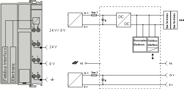
Figure 3: Potential diagram ECT-000
GND concept
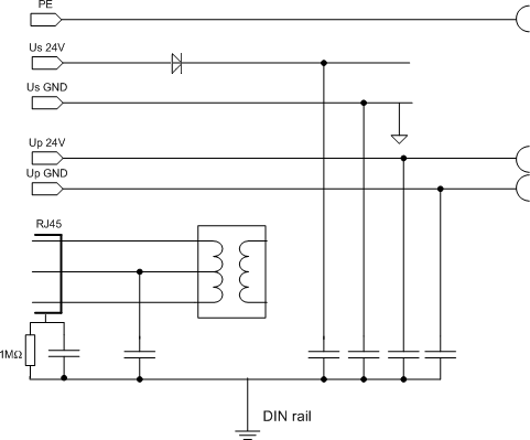
Figure 4: GND concept ECT-000
Fuse protection
| Coupler supply, fuse 1 | Depending on the required current consumption and hence the configured terminals typical max. 1 A |
| Power contacts, fuse 2 | Permitted max. 10 A (slow-blow) |
The coupler electronics and the power contacts can be supplied together from the same source. In this case the fuse should be dimensioned for 10 A max.
ECT-000 Diagnostic LEDs
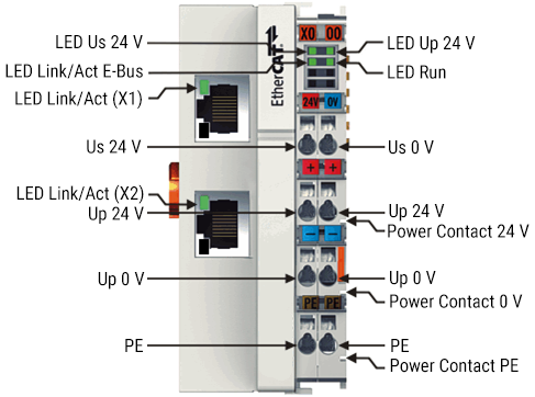
Figure 5: Diagnostic LEDs EK1100, EK1100-0008
LEDs for Power Supply Diagnostics
| LED | Display | State | Description | |
|---|---|---|---|---|
|
Us |
green |
off |
- |
No operating voltage present at the Bus Coupler |
|
on |
- |
24 VDC operating voltage present at the Bus Coupler |
||
|
Up |
green |
off |
- |
No power supply present at the power contacts |
|
on |
- |
24 VDC power supply present at the power contacts |
||
Diagnostic LEDs for the EtherCAT State Machine/PLC
| LED | Display | State | Description | |
|---|---|---|---|---|
|
RUN |
green |
off |
Init |
The Bus Coupler is in initialization state |
|
flashing |
Pre-Operational |
The Bus Coupler is in pre-operational state |
||
|
single flash |
Safe-Operational |
The Bus Coupler is in safe-operational state |
||
|
on |
Operational |
The Bus Coupler is in operational state |
||
|
flickers |
Bootstrap |
Firmware is being loaded. |
||
LEDs for Fieldbus Diagnosis
| LED | Display | State | Description | |
|---|---|---|---|---|
|
LINK/ACT (X1 IN) |
green |
off |
- |
No connection on the incoming EtherCAT strand |
|
on |
linked |
Preceding EtherCAT device connected |
||
|
flashing |
active |
Communication with preceding EtherCAT device |
||
|
LINK/ACT (X2 OUT) |
green |
off |
- |
No connection on the outgoing EtherCAT strand |
|
on |
linked |
Following EtherCAT device connected |
||
|
flashing |
active |
Communication with following EtherCAT device |
||
|
LINK / ACT E- bus |
green |
off |
- |
No connection to internal E-bus |
|
on |
linked |
Connection to internal E-bus |
||
|
flashing |
active |
Connection/communication internal E-bus |
||
Technical Data
|
Characteristic |
AKT2G-ECT-000-000 |
|---|---|
|
Protection class |
IP20 |
|
Higher level network technology |
100 MBit FastEthernet (100BASE-TX) |
|
Higher level network - max. connection length |
100 m |
|
Higher level network connection technology |
RJ45 |
|
higher-level network protocol |
EtherCAT Device Protocol |
|
supports HotConnect with address setting on the device |
yes, Fast-Hot-Connect |
|
Technical Data |
AKT2G-ECT-000-000 |
|---|---|
|
Task in the EtherCAT system |
Coupling of EtherCAT Terminals (ECT-xxx) to 100BASE-TX EtherCAT networks |
|
Number of EtherCAT Terminals |
up to 65535 in the overall system |
|
Number of peripheral signals |
max. 4.2 GB addressable IO points |
|
Data transfer medium |
Ethernet 100BASE-TX (at least Ethernet CAT5 cable) |
|
Cable length between 2 Bus Couplers |
max. 100 m (100BASE-TX) |
|
Protocol / Baud rate |
EtherCAT Device Protocol / 100 MBaud |
|
HotConnect |
no |
|
Delay |
1 µs typ. |
|
Bus connection |
2 x RJ45 |
|
Power supply |
24 VDC (-15%/+20%) |
|
Current consumption |
70 mA + (∑ E-bus current/4) |
|
E-bus power supply (5 V) |
max. 2 A (-25 °C ... +55 °C) |
|
max. 1 A (> +55 °C) |
|
|
Power contacts |
max. 24 VDC, max. 10 A |
|
Electrical isolation |
500 V (power contact/supply voltage/EtherCAT) |
|
Dimensions (W x H x D) |
approx. 44 mm x 100 mm x 68 mm |
|
Weight |
approx. 105 g |
|
Permissible ambient temperature range during operation |
-25°C ... +60°C (extended temperature range) |
|
Permissible ambient temperature range during storage |
-40°C ... + 85°C |
|
Permissible relative air humidity |
95%, no condensation |
|
Mounting |
on 35 mm mounting rail according to EN 60715 |
|
Vibration / shock resistance |
conforms to EN 60068-2-6 / EN 60068-2-27, see also Installation instructions] for enhanced mechanical load capacity |
|
EMC immunity / emission |
conforms to EN 61000-6-2 / EN 61000-6-4 |
|
Protection class |
IP20 |
|
Installation position |
variable |
|
Approval |
CE, ATEX, cULus, IECEx |