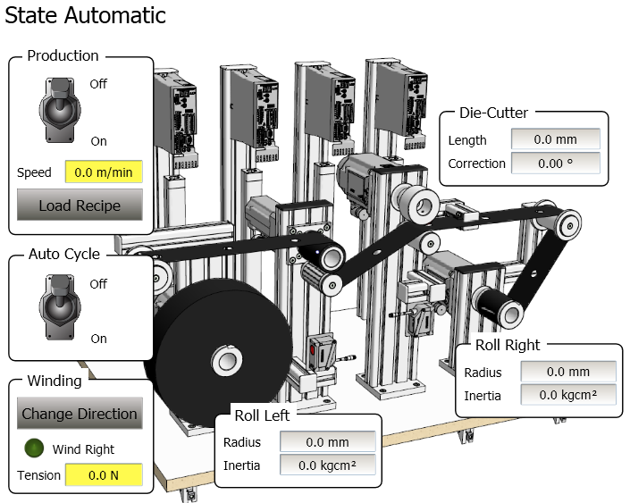
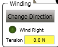
- Present wind direction
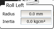
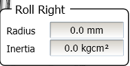
- Present roller radius and inertia of each roll
- Set Die Cutter correction value
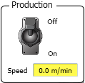
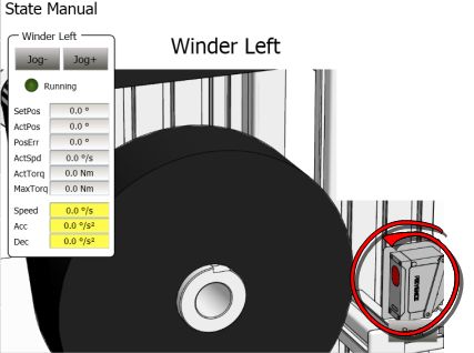
In Automatic Mode the complete machine is run. The Kollmorgen AKI has the following controls:
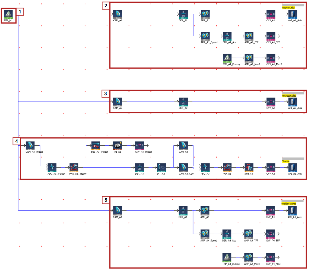
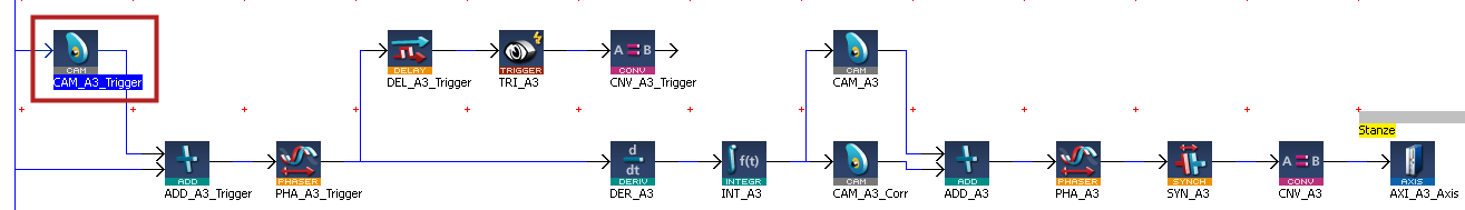
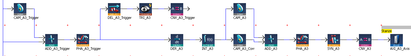
The Automatic Machine State utilizes a pipe network to create synchronized motion
 |
|
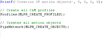
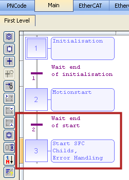
The pipe network is integrated in the runtimeIn computer science, runtime (or run-time) describes the operation of a computer program, the duration of its execution, from beginning to termination (compare compile time). Within KAS, runtime also refers to the virtual machine that manage the program written in a computer language while it is running code by the following code in the Main Program Step 1:
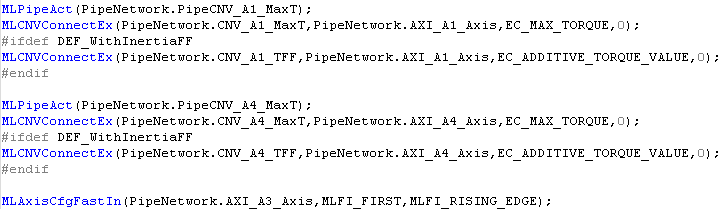
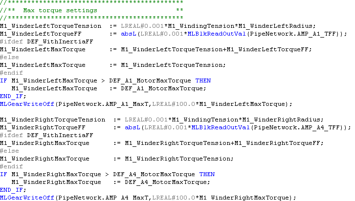
In addition, the connections for the TorqueTorque is the tendency of a force to rotate an object about an axis. Just as a force is a push or a pull, a torque can be thought of as a twist Feedforward and MaxTorque commands for Axis 1 and 4 the left and right winders not made in the pipe network need to be made. This is done by the following code in the Main Program Step 3:
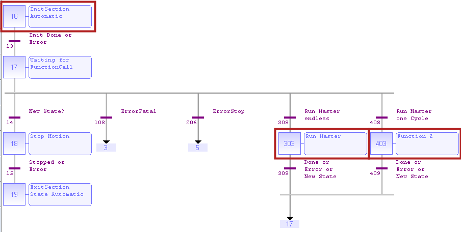
The code for the automatic mode is contained in the M1_StateController program in the following section. Step 303 is for running the master continually and step 403 is for running one cycle
| AKI | Key Parameter | Description |
|---|---|---|
INPUTS |
|
|
Production On/Off | bM1_RunMasterEndless bM1_CallAutomaticFunction1 | Turn machine on at M1_MasterSpeed |
AutoCycle On/Off | bM1_Simulator | Turns on auto running mode |
Speed | M1_MasterSpeed | Set Web speed |
Tension | M1_WindingTension | Set machine winding tension |
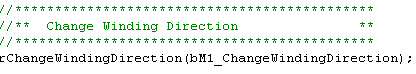
Change Direction | bM1_ChangeWindingDirection | Change direction of web movement |
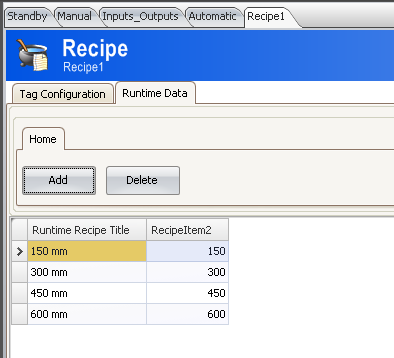
Recipe | A3_FormatLength
| Set the length between holes in web |
OUTPUTS |
|
|
Radius | M1_WinderLeftRadius M1_WinderRightRadius | Radius of the winder based on feedback from distance sensorA sensor is a type of transducer that converts one type of energy into another for various purposes including measurement or information transfer |
Inertia | M1_WinderLeftInertia M1_WinderRightInertia | Calculated inertia of the winder |
| M1_PositionPeriod = 360 | Contains the Modulo of the Virtual Master |

The pipe network contains a virtual master that sets machine speed and drives the machine. The operator enters the master speed (M1_MasterSpeed) in meters/ min. The program converts the signal to internal millimeter/sec units using the following equation:
Speed command = M1_MasterSpeed ( m/min) * 360 (degrees/rev) / 60 (sec/min) * 1000(mm/m) / 150 (degrees/rev) = XXXX mm/sec
(XXXX meter/min) / (60 sec/min) * (1000 millimeter/meter) / Draw Roller PosPeriod = YYYY millimeter/sec
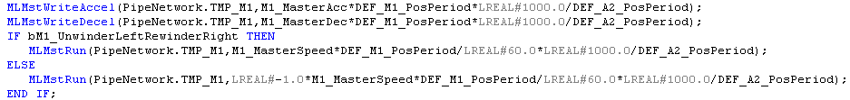
The code to set the accel and decel rates and to also run the virtual master is in step 303 of the M1_StateController program:
 ;
;
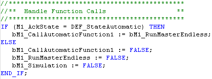
The following code reads the machine On/Off input and directs the program to enter step 303:
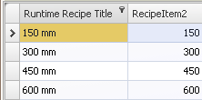
Load Recipe sets the length between holes in the web. The options are: 150 300, 450, 600 mm. The change is length is implemented in the pipe network by adjusting the Profiles.Corr adjusts the profile used in the CAM_A3_Corr CAM block in the pipe network for axis 3.

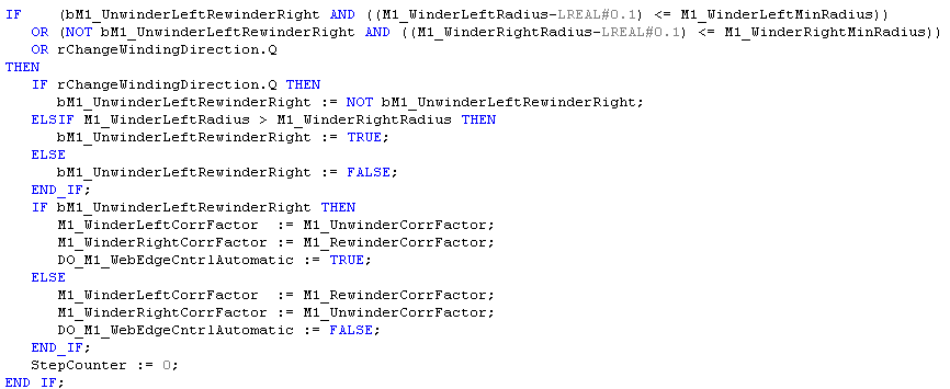
The direction of the web will change once the roll diameter gets below a minimal diameter or a request to change direction is given. The code for this is in Step 303:
The tensions on the left and right winders are set by the present radius of the winder multiplied by a WindingTension value set in the Kollmorgen AKI. The following code is in the Main program step 3:
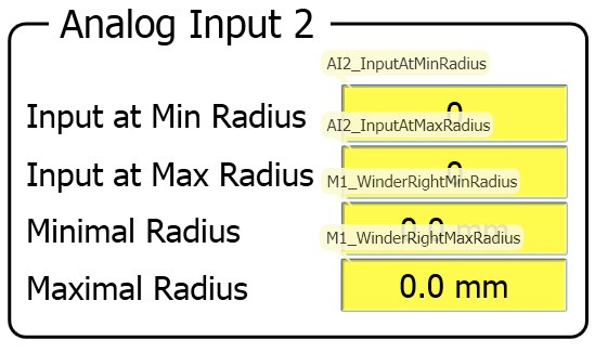
The program calculates the roll inertia and radius in the M1_Interface program for both the left and right roller
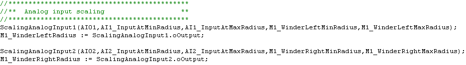
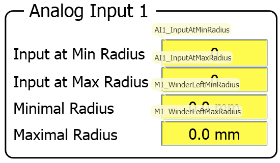
Roll Radius is calculated based on the value of an analog input from a distance sensor. The subprogram fbAnalogInputScaling is used to scale the input

The following shows the code for the left winder
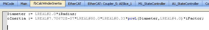
Inertia is calculated using the fbCalcWinderInertia subprogram:
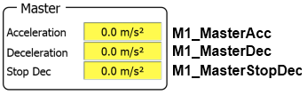
The Kollmorgen AKI displays the values:
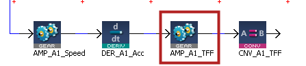
The Torque Feedforward scale factor in the pipe network is then set proportional to the inertia of the roll.
The following is from the M1_Interface Program
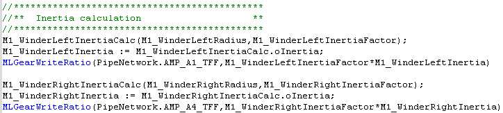
Code Location: M1_Interface
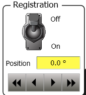
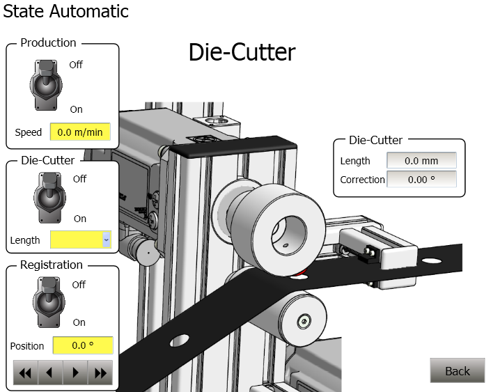
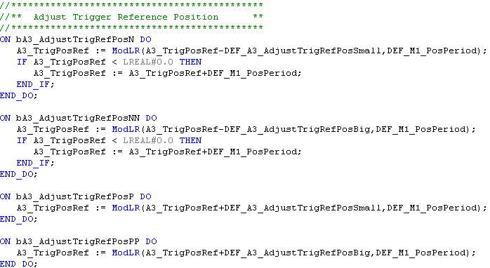
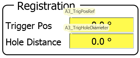
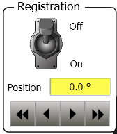
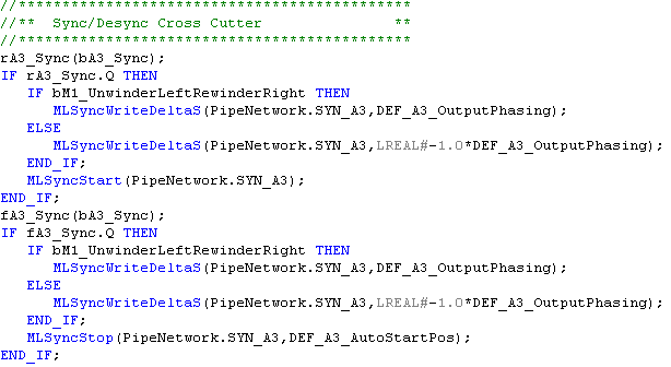
The following code processes the registration adjustment control on the HMI"Human-machine interfaces " Also known as computer-human interfaces (CHI), and formerly known as man-machine interfaces, they are usually employed to communicate with PLCs and other computers, such as entering and monitoring temperatures or pressures for further automated control or emergency response. It allows the machine operator to fine tune the registration position:
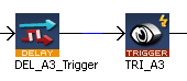
Code Location: Program - M1_Interface
The following code then takes the A3_Trigger offset value and makes a phase adjust to Axis 3 die cutter position by using the function block: MLPrfWriteOScale (Profiles.Trigger, A3_Correction) with changes the output scaling of the CAM_A3_Trigger CAM block.
Code Location: Main Step 3N
The Kollmorgen AKI displays the following:

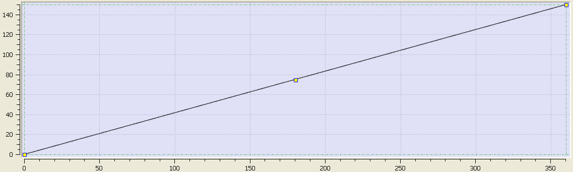
The pipe for each axis contains a CAM_Ax pipe network block labelled as CAM_A1, CAM_A2, CAM_A3, and CAM_A4 respectively for the 4 axis. The purpose of these blocks is to normalize the amount of movement of each axis for one cycle of the Die Cutter. The period of the CAM is set to DEF_A1_PosPeriod in the CAM block setup:
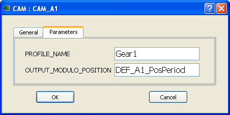
A1_PositionPeriod = 360
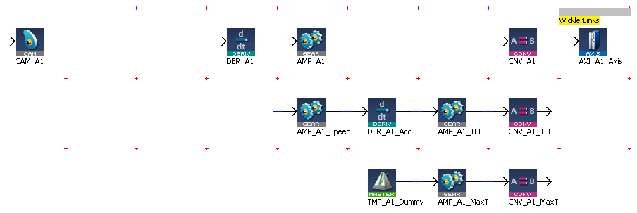
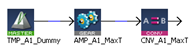
The left winder is connected to the virtual master through a set of pipe network transmission blocks which output 3 signals to the drive through Ethercat: Position Command, Torque Feed Forward Command, and Max Current command

The position command is created by the pipe network as follows:
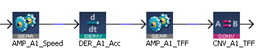
The Torque feed forward command is created by the pipe network as follows:


The inertia of the winders is determined by the fbCalcWinderInertia subprogram as follows:
This sets the tension of the left roller. The pipe network algorithm starts with a dummy speed command set to zero. The offset value on a GEAR pipe network block is used to set a max torqueTorque is the tendency of a force to rotate an object about an axis. Just as a force is a push or a pull, a torque can be thought of as a twist limited value to the drive through EtherCATEtherCAT is an open, high-performance Ethernet-based fieldbus system. The development goal of EtherCAT was to apply Ethernet to automation applications which require short data update times (also called cycle times) with low communication jitter (for synchronization purposes) and low hardware costs. The value is a function of the roll diameter and the present value. The winding Tension of the left roller is set by the equation:

M1_WindingTension is set by the machine operator. M1WinderLeft Radius is determined by an external sensor. The value is read and sent through the following filter:
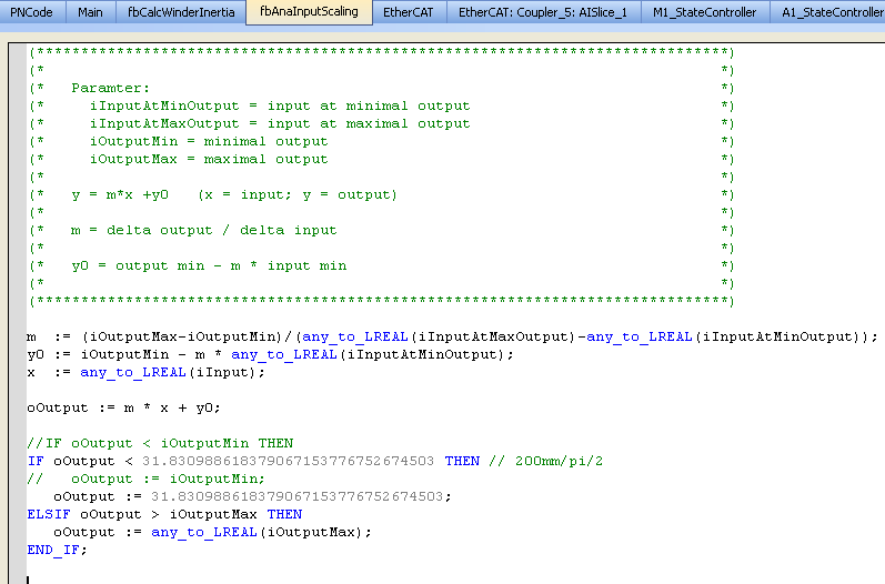
oOutput is loaded into the parameter: M1WindingLeftRadius
A2_PositionPeriod = 150
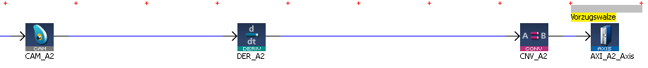
The command to the Draw Roller is the speed command from the virtual master. The CAM_A2 CAM PN block is used to rescale the Master input to 150/360 x the input. The DER_A2 Derivate PN block prevents any motion jumps when the TMP"Trapezoidal Motion Profile" This pipe block is a source block that frequently serves as a virtual master for a system composed of several pipes. Generally, a trapezoidal motion profile generator is used to generate a flow of values with a first derivative which produces a trapezoidal trajectory master goes through the modulo.
A3_PositionPeriod = 300
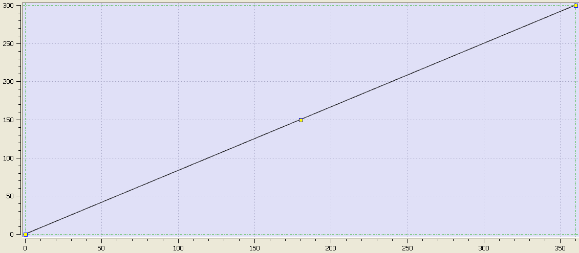
The die cutter speed is determined by the equation:
Die cutter (linear speed) speed = Line speed.
The line speed is determined by a user input to the TMP Master PN block.
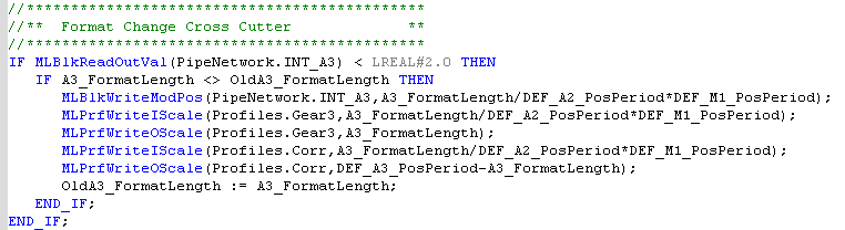
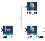
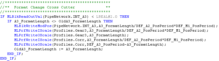
Changing the Die cutter operation for different lengths between cuts is accomplished by changing the modulo value of the INT_A3 PN block and changing the input and output scaling of the CAM_A3 and CAM_A3_Corr PN blocks.
Scaling of the length from user units of xxx to mm units of degrees is done as follows:
Internal value = A3_FormatLength X (normalization factor of 150mm = 360 Degrees)
= A3_FormatLength / DEF_A2_PosPeriod * DEF_M1_PosPeriod
= A3_FormatLength / 150 * 360 degrees movement of the die cutter
150 mm travel of web = 360 degrees
The code is located in the Main Program Step 3:
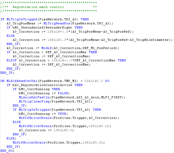
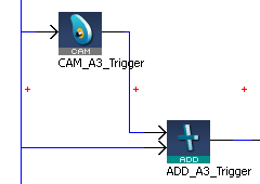
Phase adjusting the die cutter position with respect to the web to account for slippage is accomplished by using a high speed input to capture a pipe network position then comparing this position to the needed PN position. The Registration position can be offset for the Kollmorgen AKI:
The code is located in the Main Program Step 3
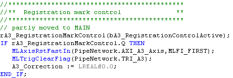
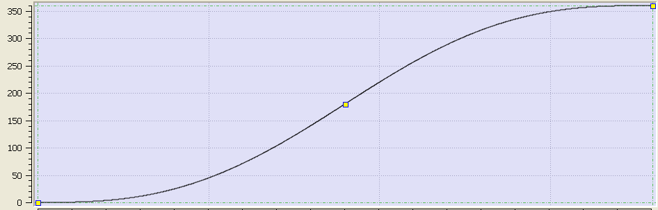
The position difference is then added or subtracted from the pipe using a CAM block. The cam block is used to smoothly make the phase adjust motion.
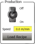
The die cutter can be turned on and off from the Kollmorgen AKI:
A4_PositionPeriod = 360
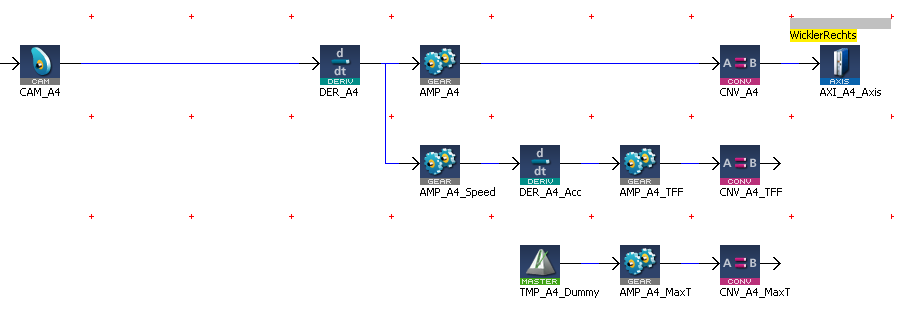
The left winder code and explanation is similar to the right winder.
The following is one of the Kollmorgen API screens for this application.
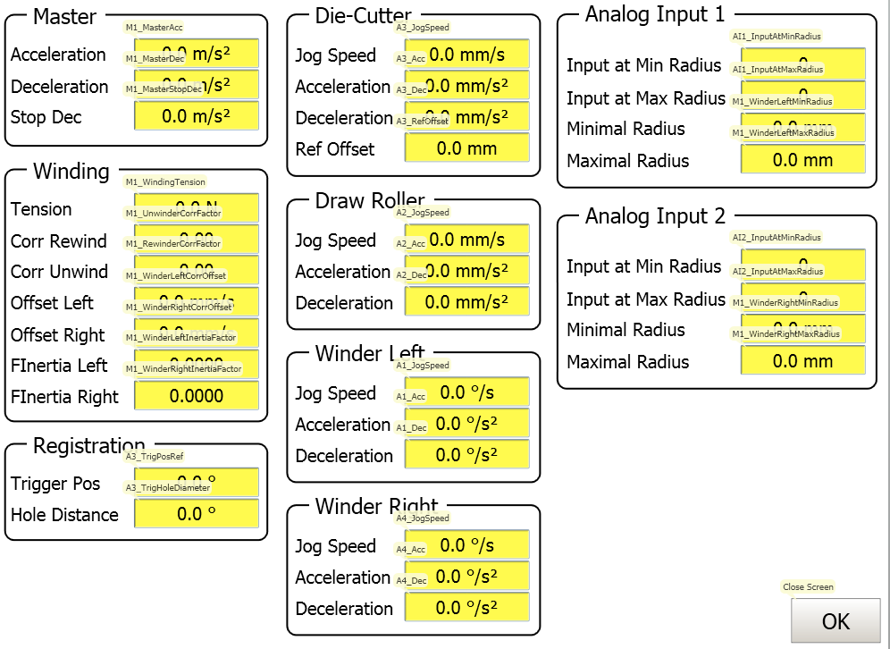
Stay Connected with Kollmorgen        | Copyright © 2015 Kollmorgen™ |  |