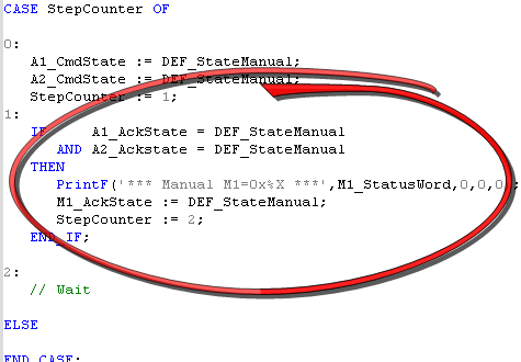
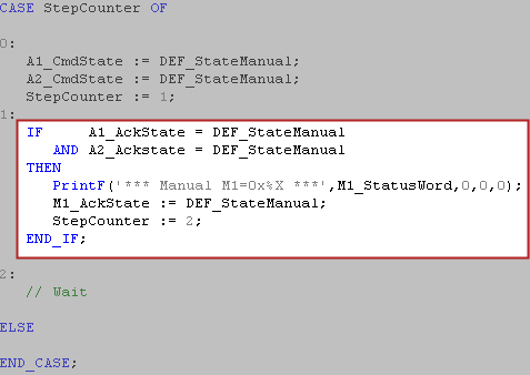
The following code executes this process when going into the Manual state:
The project has a built-in state controller that controls which machine state is active. A set of variables are used to move the state machine between states. For more information see Standard MachineThe complete assembly of all connected parts or devices, of which at least one is movable Template for PN Motion with SFC"Sequential function chart" It can be used to program processes that can be split into steps. The main components of SFC are: - Steps with associated actions - Transitions with associated logic conditions - Directed links between steps and transitions/ST"Structured text" A high-level language that is block structured and syntactically resembles Pascal programming language and the document KAS_MachineTemplate_V1_1.pdf for more information.
| State | Description |
|---|---|
|
Standby |
No faults, drives not enabled |
|
Manual |
No Faults, Manual Jog operation |
|
Automatic |
No Faults, Multi-axis machine operation |
|
Error Stop |
Fault state, not a fatal fault |
|
Error Fatal |
Fault state, fatal fault(s) |
Program Type: SFC
The Main Program is automatically executed when the project starts. This program initializes the pipe network motion and EtherCATEtherCAT is an open, high-performance Ethernet-based fieldbus system. The development goal of EtherCAT was to apply Ethernet to automation applications which require short data update times (also called cycle times) with low communication jitter (for synchronization purposes) and low hardware costs network:
Code Location: Main Program Step 1 and 2:
| Parameter | Description |
|---|---|
|
MLMotionInit(1000.0) |
Initializes the motion engine |
|
Profiles(MLPR_CREATE_PROFILES); |
Creates all CAM profiles |
| PipeNetwork(MLPN_CREATE_OBJECTS) | Creates all motion objects |
|
MLMotionStart() |
Starts the motion engine |
In the Main program step 3 there are other sections of code to:
Program Type: SFC
M1_StateController controls the state or operation mode of the application. The following states are supported: Standby, Manual, Automatic, Error Stop and Error Fatal. On application start-up, the state machine goes into the Standby mode. The state or mode is then changed to one of the others in one of the following ways:
After the error condition is cleared, clicking on the reset button in the internal Control Panel or Kollmorgen AKI will send the M1_State controller back to the previous state (typically Manual or Automatic Mode).
M1_StateController contains functions to perform the multi-axis motion defined in the Automatic Mode and shown in the M1_Panel control panel.
| Parameter | Description |
|---|---|
|
M1_CmdState
|
Contains the actual state command value. It is automatically set to state ‘Standby’ during power up //********************************************* //** State Defines //********************************************* #define DEF_StateUndefined 0 #define DEF_StateStandby 1 #define DEF_StateManual 2 #define DEF_StateAutomatic 3 #define DEF_StateBusy 4 #define DEF_StateErrorStop 5 #define DEF_StateErrorFatal 6. |
|
M1_AckState |
Contains the actual state acknowledge value, as a result of a successfully performed state command (M1_CmdState).. |
|
M1_ReqState |
Contains the internally active state. It is used for internal purposes only, to keep the actual state value, e.g. while performing a function. Possible values are the same as for the state commands (see above). |
|
M1_StatusWord |
Main Status Word |
|
bM1_CallAutomaticFunction1 |
Received from M1_Interface and used to execute a Run Master Endless Operation |
|
bM1_CallAutomaticFunction2 |
Received from M1_Interface and used to execute a Run Master One Cycle Operation |
Program Type: SFC
There is one for each axis. Ax_StateController controls the state or operation mode of an individual axis. The following states are supported: Standby, Manual, Automatic, Error Stop and Error Fatal. On application start-up the state machine goes into the Standby state, as requested from the M1_StateController. The state is then changed to one of the other states in one of the following ways:
| Parameter | Description |
|---|---|
|
A1_CmdState A2_CmdState |
Contains the actual state command value. It is automatically set to state ‘Standby’ during power up //********************************************* //** State Defines //********************************************* #define DEF_StateUndefined 0 #define DEF_StateStandby 1 #define DEF_StateManual 2 #define DEF_StateAutomatic 3 #define DEF_StateBusy 4 #define DEF_StateErrorStop 5 #define DEF_StateErrorFatal 6 |
|
A1_AckState A2_AckState |
Contains the actual state acknowledge value, as a result of a successfully performed state command (M1_CmdState). |
|
A1_ReqState A2_ReqState |
Contains the internally active state. It is used for internal purpose only, to keep the actual state value, e.g. while performing a function. Possible values are the same as for the state commands (see above). The change is made when AckState changes to Busy |
|
A1_StatusWord A2_StatusWord |
Axis Status Word |
|
bA1_CallManualFunction1 bA2_CallManualFunction1 |
Received from the M1_Interface program and used to execute a Run Master Endless Operation |
|
bA1_ CallManualFunction2 bA2_CallManualFunction2 |
Received from the M1_Interface program and used to execute a Run Master One Cycle Operation |
M1_ErrorHandler executes the MainErrorHandler subprogram which outputs the machine status parameter: M1_StatusWord. For more detail see section 6: ErrorHandler.
|
Stay Connected with Kollmorgen       
|
Copyright © 2015 Kollmorgen™ |

|