FAQs
Basic
Your Autorun feature may be deactivated. Open an Explorer window to see the autorun.exe file and use the Run command in the contextual menu to manually start the installer.
That depends on the version of KAS. You may have one version of KAS IDE![]() "Integrated development environment"
An integrated development environment is a type of computer software that assists computer programmers in developing software.
IDEs normally consist of a source code editor, a compiler and/or interpreter, build-automation tools, and a debugger v3.00 and earlier installed along with any number of later versions.
"Integrated development environment"
An integrated development environment is a type of computer software that assists computer programmers in developing software.
IDEs normally consist of a source code editor, a compiler and/or interpreter, build-automation tools, and a debugger v3.00 and earlier installed along with any number of later versions.
| KAS version | Only 1 version |
|
|---|---|---|
| < v3.00 |

|

|
| v3.01 and later |

|

|
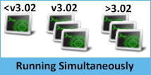
Yes, as long as one of the versions is v3.02 or later. With the release of v3.02 multiple instances of the KAS IDE are permitted. That includes running one older (<v3.02) instance and any number of newer instances. This includes multiple instances of the same version. The only limitation is available RAM.
-
- The KAS IDE supports simultaneously running multiple instances. Double-clicking a shortcut or project file, or selecting the application from the Start menu will open another instance, Double-clicking on a project file more than once will open a copy of the project in another instance of the KAS IDE.
Right-clicking on a project file allows you to choose which of your installed versions of the KAS IDE to use for that instance.

Yes, the KAS IDE supports copying and pasting between simultaneously running instances. This is supported in both the same version and different version numbers. This includes drag and drop for supported objects, such as FBD blocks.
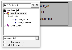
The KAS IDE will attempt to recreate what you have copied, but there are some limitations. For example, it may not automatically associate variables with a function. For example, if you copy and paste only a function block from an FFLD program, the assigned variables will not be copied and pasted, but if you select the entire network the KAS IDE will automatically create the variables for you.
|

|
| Copying a block | Copying an entire network recreates assigned variables in the Dictionary |
-
- Closing the KAS IDE automatically clears the Clipboard. Anything that was copied is cleared from memory. This means you can not copy something, close the KAS IDE, and then paste.
A side effect with some remaining files that were not deleted properly can interfere with your new project. To fix this issue:
- Close your current project without saving
- Open Windows Explorer and go to C:\Documents and Settings\(user)\Local Settings\Application Data\Kollmorgen\KAS\Project , where “(user)” is the Windows' username you are currently logged in with
- Delete all the remaining files and folders
- You can now create your new project
Everything in our manuals may be found in the help. If you need a printable document or want stand-alone manuals, the documentation is available as PDFs on KDN.
With the AutoSave function, project files are saved for recovery. More than one file may exist due to multiple versions of the KAS IDE being installed or used. When you restart the KAS IDE you will be prompted to recover a found file. When there is more than one file the recovery process will start with the latest date from the newest KAS IDE version. Assuming you choose to recover the file it is opened and you may resume work, but the older recovery files still exist.
The next time you launch the KAS IDE you will be prompted to recover the next oldest file. Choosing to not recover the file will delete it, and you will be prompted to open the next oldest file until none are left.
Setup
As depicted in figures found in Different Implementations, the fieldbus serially links all the drives to the industrial PC.
-
-
When the KAS IDE is used to deploy an automation system on a master drive (also known as programmable drive), the fieldbus serially links all the drives to the master drive.
As described in Communication and Fieldbus, KAS can communicate with outside world through Ethernet![]() Ethernet is a large, diverse family of frame-based computer networking technologies that operate at many speeds for local area networks (LANs), CANopen, DeviceNet
Ethernet is a large, diverse family of frame-based computer networking technologies that operate at many speeds for local area networks (LANs), CANopen, DeviceNet![]() DeviceNet is a communication protocol (based on Controller Area Network) used in the automation industry to interconnect control devices for data exchange. Typical applications are information exchange, safety devices, and large I/O control networks.
DeviceNet is a communication protocol (based on Controller Area Network) used in the automation industry to interconnect control devices for data exchange. Typical applications are information exchange, safety devices, and large I/O control networks.
This issue occurs when you perform the following
- Connect to the controller and download your application
- In the project explorer, open the EtherCAT
 ***EtherCAT is an open, high-performance Ethernet-based fieldbus system. The development goal of EtherCAT was to apply Ethernet to automation applications which require short data update times (also called cycle times) with low communication jitter (for synchronization purposes) and low hardware costs properties
 - Click theOnline Configuration Mode
- In the project explorer, right-click on the AKD_1 and select Load/Save Parameter…
- Then select the Factory Defaults… command to reset the drive to its default parameters
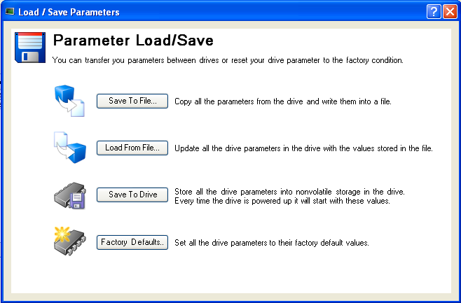
- Clicking the Online Configuration Mode leads to the following error

Reason
If you set the drive to its default parameters, then all the AKD parameters are restored and the unique ID (FBUS.PARAM03) used to identify the drive is lost.
Solution
You have to perform a new scan operation after setting the parameters to its default values
-
-
You can also clear the Write a unique ID option in the XML
 "Extensible Markup Language "
XML is a general-purpose markup language. It is classified as an extensible language because it allows its users to define their own tags configuration tab (for more details, ENI File Tab)
If you encounter any security issues during execution of Kollmorgen Automation Suite, refer to your IT department to set your proxy properly.
You may have to define your firewall settings to allow accessing the IP addresses used by KAS (for instance, IP address of the target system, or localhost IP address for the KAS Runtime![]() In computer science, runtime (or run-time) describes the operation of a computer program, the duration of its execution, from beginning to termination (compare compile time).
Within KAS, runtime also refers to the virtual machine that manage the program written in a computer language while it is running Simulator: 127.0.0.1).
In computer science, runtime (or run-time) describes the operation of a computer program, the duration of its execution, from beginning to termination (compare compile time).
Within KAS, runtime also refers to the virtual machine that manage the program written in a computer language while it is running Simulator: 127.0.0.1).
Port numbers have to be set properly in your firewall settings to avoid any trouble during communication, such as when downloading the application to the target, or plugging a probe to the softscope. Kollmorgen strongly recommends opening port numbers over 1024, as well as the range 502 to 520.
Computer / Controller
This number is mainly dependent upon the application and your PC's computing power. An average number would be 20 axes/ms
This procedure allows you to determine if your controller is overloaded due to the PLC![]() "Programmable Logic Controller"
A Programmable Logic Controller, PLC, or Programmable Controller is a digital computer used for automation of industrial processes, such as control of machinery on factory assembly lines.
Used to synchronize the flow of inputs from (physical) sensors and events with the flow of outputs to actuators and events program or motion system load.
"Programmable Logic Controller"
A Programmable Logic Controller, PLC, or Programmable Controller is a digital computer used for automation of industrial processes, such as control of machinery on factory assembly lines.
Used to synchronize the flow of inputs from (physical) sensors and events with the flow of outputs to actuators and events program or motion system load.
You can use the Softscope and the Trace Times button to display the following CPU loads:
- CycleJitter (microseconds)
- Motion execution time (microseconds)
- PLC execution time (microseconds)
- Real Time Margin (microseconds)
To view the load, do as follows:
- Open the Softscope
- Plug four probes to any kind of data (see procedure here)
- In the Control Panel, click the TraceTimes button
If you are unable to log into the controller's webpage using a valid user ID and password, the controller's file system may be corrupt. To recover the system you will need to use the push buttons on the controller (see Booting from the Recovery Image) to recover the system.
Graphics need to be made portable with a project, otherwise the KAS IDEwill attempt to point to the original location of the graphic files. To make graphics portable, copy them to c:\Users\[user folder]\AppData\Local\Kollmorgen\Project\Controller\PLC. After this the graphics are a part of the .KAS file.
Performance
Due to excessive ASCII SDO commands or very slow Ethernet communication, the WorkBench tree may not fully populate or navigation may be unresponsive. To recover from this situation:
- Press the Refresh Tree button in KAS IDE WorkBench view.
- Disconnect and Reconnect the KAS IDE to restart KAS IDE-WorkBench communication.
The status bar may display a warning if communication between the KAS IDE, controller, and drive is too slow.

To begin troubleshooting, configure the Local log for WARNING level (or lower) and check for "communication too slow" messages. The IDE-WorkBench navigation and views may become very slow or completely unresponsive if the average response time for drive communication is too long.
Communication delays between the KAS IDE and Controller can be caused by degraded Ethernet bandwidth![]() In computer networking, bandwidth often refers to a data rate measured in bits/s, for example, network throughput. The reason for the connection of data rate with the term bandwidth is that the limit to the data rate of a physical communication link is related to its bandwidth in hertz or high latencies. You can use the Windows Resource Monitor (resmon.exe) and select kas_ide.exe to monitor and diagnose high latency and/or poor bandwidth.
In computer networking, bandwidth often refers to a data rate measured in bits/s, for example, network throughput. The reason for the connection of data rate with the term bandwidth is that the limit to the data rate of a physical communication link is related to its bandwidth in hertz or high latencies. You can use the Windows Resource Monitor (resmon.exe) and select kas_ide.exe to monitor and diagnose high latency and/or poor bandwidth.
Communication delays between the Controller and Drive can occur while an application is running on the controller. Degraded drive communication can be caused by excessive ASCII SDO commands from the application code.
- Check your application code for calls to DriveParamRead/Write(...), DriveParamStrRead(...), or ECATRead/WriteSdo(...), and minimize the frequency of these calls.
- Use Online Configuration Mode with KAS IDE WorkBench to avoid ASCII SDO channel competition between your application and KAS IDE WorkBench
There are times when trying to connect to multiple drives simultaneously with WorkBench is problematic, particularly on slower networks.
To resolve this situation:
- Close all of the open windows in the IDE workspace, leaving only one WorkBench window open.
- Connect the KAS IDE and run the project or use Online Configuration mode.
These actions reduce the network and KAS IDE loads. This allows the embedded WorkBench to establish communication and access the views.
To access multiple drives at the same time:
- Open one WorkBench window
- Wait for communication and initialization to complete successfully
- Open each additional WorkBench window one at a time, allowing enough time for each to successfully complete initialization.
EtherCAT
No. As with every real-time Industrial Ethernet system, one device (the master) has to be in charge of the network management and organize the Medium Access Control. With EtherCAT, Slave-to-Slave communication is supported in two ways:
- topology dependent within one communication cycle ("upstream" device talks to "downstream" device)
- topology independent within two cycles.
Since EtherCAT is so much faster than competing systems, slave-to-slave communication using two cycles is faster, too.
The maximum number of node addresses is 65,535. Typically, the number of the nodes on the network will be limited by the maximum EtherCAT frame size, which is 1500 bytes. Please see the Frame![]() In networking dialect, a message is called a frame Size in the EtherCAT Master Settings Tab for more details.
In networking dialect, a message is called a frame Size in the EtherCAT Master Settings Tab for more details.
If you need to rely on SDO communication to set the parameter of an EtherCAT device, you can do this with the ECATWriteSdo FB (see alsoEtherCAT Library).
Being asynchronous and based on the EtherCAT mailbox, the SDO communication is not deterministic. So the EtherCAT master uses a polling mode to ensure the SDO command is completed. Note that in operational mode, this polling is performed every 50 cycles 1 . As a consequence, you can expect the acknowledgement of your SDO command usually before less than 100 ms. So, a good practice is to set the update rate for SDO communication in your PLC application each 25 cycles.
EtherCAT Motion Bus Concepts for more details.
The AKD2G has a limit on the number of PDO![]() PDO is a type of protocol frame used in some fieldbuses. A PDO contains one or more object dictionary entries, which define the application data transferred between devices. objects which can be mapped, depending upon the sample rate.
PDO is a type of protocol frame used in some fieldbuses. A PDO contains one or more object dictionary entries, which define the application data transferred between devices. objects which can be mapped, depending upon the sample rate.
| Sample Rate | Cycle Time | Max. PDOs |
|---|---|---|
| 4kHz | 250μs | 14 Rx, 14 Tx |
| 2kHz | >500μs | 30 RX, 30 Tx |
This limitation can be hit during compilation with the following error:
EtherCAT: ERROR: In AKD2G_1, the total number of entries for all selected Tx PDOs is greater than the max allowed at a cycle time of 250 μs: 17 > 14
There are three possible solutions.
- Increase the Cycle Time – see EtherCAT Master Settings Tab
- Deselect unused PDOs – see PDO Selection/Mapping Tab
- Delete unused objects – see Delete a CoE Object
Programming
When you want to check the maximum time execution for an SFC![]() "Sequential function chart"
It can be used to program processes that can be split into steps.
The main components of SFC are:
- Steps with associated actions
- Transitions with associated logic conditions
- Directed links between steps and transitions step, you have to program this action based on the SFC alarm capability.
"Sequential function chart"
It can be used to program processes that can be split into steps.
The main components of SFC are:
- Steps with associated actions
- Transitions with associated logic conditions
- Directed links between steps and transitions step, you have to program this action based on the SFC alarm capability.
To show this status, you have to:
- In the Dictionary, declare a Boolean PLC variable linked to the related SFC program

- Add the instruction in the Actions tab related to the SFC step, with first parameter set to A (for Alarm) as shown below

The syntax is explained here.
More details on the timeout on an SFC step are also given here.
If you open a project containing a link on a library which is no longer available, a warning is displayed. To fix this issue, refer to What happens when a library no longer exists?
The Fast Input![]() The inputs are taken into account at each cycle depending on the system periodicity (for example each millisecond). Under certain circumstances this can be insufficient when more accuracy is needed, or if a quick response is required from the system. To fill the gap, a drive may have some Fast Input connections (generally one or two). When an event happens that triggers a Fast Input (e.g. when a sensor sends a rising edge), the detection of a signal occurs faster (which can be 1000 times more accurate than the system periodicity). Then the timestamp associated with this input can be provided to the IPC to take corrective action allows an application to get information about the occurrence of an external event at a higher resolution than the cycle time.
The inputs are taken into account at each cycle depending on the system periodicity (for example each millisecond). Under certain circumstances this can be insufficient when more accuracy is needed, or if a quick response is required from the system. To fill the gap, a drive may have some Fast Input connections (generally one or two). When an event happens that triggers a Fast Input (e.g. when a sensor sends a rising edge), the detection of a signal occurs faster (which can be 1000 times more accurate than the system periodicity). Then the timestamp associated with this input can be provided to the IPC to take corrective action allows an application to get information about the occurrence of an external event at a higher resolution than the cycle time.
For more details, refer to Fast Inputs with Pipe Network Motion
There are two kinds of feedback:
Primary feedback
With a S300![]() "Servostar 300 drive"
See Servo Drive in Glossary drive you can use a resolver for primary feedback.
"Servostar 300 drive"
See Servo Drive in Glossary drive you can use a resolver for primary feedback.
Secondary feedback
If a secondary feedback is required with your S300 drive, you can use a BiSS![]() "Bi-directional Serial Synchronous interface"
An open-source communication protocol for feedback devices. With BiSS, all of the computation for interpolation in regard to position occurs on the ASIC directly in the encoder feedback device
"Bi-directional Serial Synchronous interface"
An open-source communication protocol for feedback devices. With BiSS, all of the computation for interpolation in regard to position occurs on the ASIC directly in the encoder feedback device![]() A process whereby some proportion of the output signal of a system is passed (fed back) to the input.
In automation, a device coupled to each motor to provide indication of the motor's shaft angle, for use in commutating the motor and controlling its speed and position.
A process whereby some proportion of the output signal of a system is passed (fed back) to the input.
In automation, a device coupled to each motor to provide indication of the motor's shaft angle, for use in commutating the motor and controlling its speed and position.
If you use the same setup with an S300 drive, the S300's EXTPOS parameter has to be set to -11.
IMPORTANT: do not omit the negative sign!
To access secondary feedback, use a SAMPLER Pipe Network block. To configure the block use the MLSmpConPNAxis, MLSmpConPLCAxis, or MLSmpConECAT functions.
Current drives that support torque![]() Torque is the tendency of a force to rotate an object about an axis. Just as a force is a push or a pull, a torque can be thought of as a twist feed-forward
Torque is the tendency of a force to rotate an object about an axis. Just as a force is a push or a pull, a torque can be thought of as a twist feed-forward![]() This describes an element or pathway within a control system which passes a controlling signal from a source in the control system's external environment, often a command signal from an external operator, to a load elsewhere in its external environment are: S300 and AKD drives.
This describes an element or pathway within a control system which passes a controlling signal from a source in the control system's external environment, often a command signal from an external operator, to a load elsewhere in its external environment are: S300 and AKD drives.
To use torque feed-forward, you have to rely on a CONVERTER Pipe Network block. To configure the block use the MLCNVConnectEx function. The arguments must be:
- The Pipe Network block ID being configured
- The ID of the axis to which the torque feed-forward is applied
- The constant EC_ADDITIVE_TORQUE_VALUE
- An ignored integer value (usually set to zero)
For more details, refer to the three following links:
If I measure a number e.g. 500 as an input at the Convertor block which is connected with the PDO object (Additive Torque![]() Torque is the tendency of a force to rotate an object about an axis. Just as a force is a push or a pull, a torque can be thought of as a twist Value 0x60B2), how many Amps are fed in the current loop at the AKD?
Torque is the tendency of a force to rotate an object about an axis. Just as a force is a push or a pull, a torque can be thought of as a twist Value 0x60B2), how many Amps are fed in the current loop at the AKD?
Current loop feed-forward value = Rated current x IL.KBUSFF x input at converter block / 1000
For example, with an AKD where:
| Rated current | 3A |
| IL |
1.0 |
| Additive Torque (PDO object) | 500 units |
Then
IL.FF = 3 x 1.0 x 500 / 1000
IL.FF = 1.5A
There is no limitation with the cams, the number of cams, the number of cam points, etc.. The limitation is only given by the processing power of your PC.
Pipe Blocks Description for more details.
Yes, I/O points represent the state of real world values.
This item is explained here
The system needs to know where to place the copied blocks. Press Ctrl-V then use the mouse to point to where you want the copied blocks to be pasted.
There are network and mechanical delays in systems that will make capturing a correct pipe position difficult. To remove the delays, you should use a sampler block to capture the actual position of an axis. The following shows how this works.
The sampler block above is configured to capture the actual position of axis 1. The conversion and axis blocks are only needed to terminate the pipe. MLTrigWriteDelay may still be needed to compensate for sensor![]() A sensor is a type of transducer that converts one type of energy into another for various purposes including measurement or information transfer delay.
A sensor is a type of transducer that converts one type of energy into another for various purposes including measurement or information transfer delay.
If you need to calculate the master pipe value corresponding to the captured axis position, you need to add the difference between the axis command position and the master pipe value.
If a hardware limit flag is being triggered at the program startup by a PipeNetwork axis, MLAxisReAlign may need to be called immediately before motion occurs. In this case, the distance to travel should be at least as long as the maximum distance the hardware limit flag can remain active.
