How To Create a Digitizing Axis
Digitizing axes are supported by PLCopen![]() A vendor -and product- independent worldwide association active in Industrial Control and aiming at standardizing PLC file formats based on XML-based projects. Following is the general process. The specifics will vary depending upon your EtherCAT
A vendor -and product- independent worldwide association active in Industrial Control and aiming at standardizing PLC file formats based on XML-based projects. Following is the general process. The specifics will vary depending upon your EtherCAT![]() ***EtherCAT is an open, high-performance Ethernet-based fieldbus system. The development goal of EtherCAT was to apply Ethernet to automation applications which require short data update times (also called cycle times) with low communication jitter (for synchronization purposes) and low hardware costs network.
***EtherCAT is an open, high-performance Ethernet-based fieldbus system. The development goal of EtherCAT was to apply Ethernet to automation applications which require short data update times (also called cycle times) with low communication jitter (for synchronization purposes) and low hardware costs network.
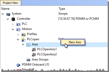
- From the Project View, right-click on the Controller > Motion > PLCopen item and select New Axis.

- Give the axis a name, note that spaces are not supported. See Common Axis Parameters for details.
- Digitizing axes have Bus data which needs to be defined. See Digitizing Axis Parameters for details.
- Lastly, define the Axis Data Parameters.
The following list provides more detail about each method or circumstance under which a digitizing axis may be created.
- How To Create a Digitizing Axis When EtherCAT Devices Are Defined
- How To Create a Digitizing Axis When EtherCAT Devices Are Not Connected
- How To Create a Digitizing Axis When Using an Imported ENI File
- How To Create a Digitizing Axis From Code
Also see Working With A Digitizing Axis in PLCopen for more in-depth information about digitizing axes.
The feedback position will become zero if the device providing the Feedback Position for the Digitizing axis is removed using the ECATDeviceAction function block. The feedback position data coming from the device will automatically be connected to the digitizing axis when the device is reconnected to the EtherCAT network.


